Category Archives: Instructions

instructions for the chevrolet chevelle ss 1966 model pdf

Article Plan: 1966 Chevrolet Chevelle SS ⎻ PDF Instructions

Discover comprehensive PDF guides for restoring your 1966 Chevrolet Chevelle SS! Access detailed instructions, from headliner installation to manual transmission specifics, and air conditioning add-on kits.

Find evaporator removal procedures, steering system details, and crate engine information – all readily available in downloadable PDF formats for a seamless restoration experience.

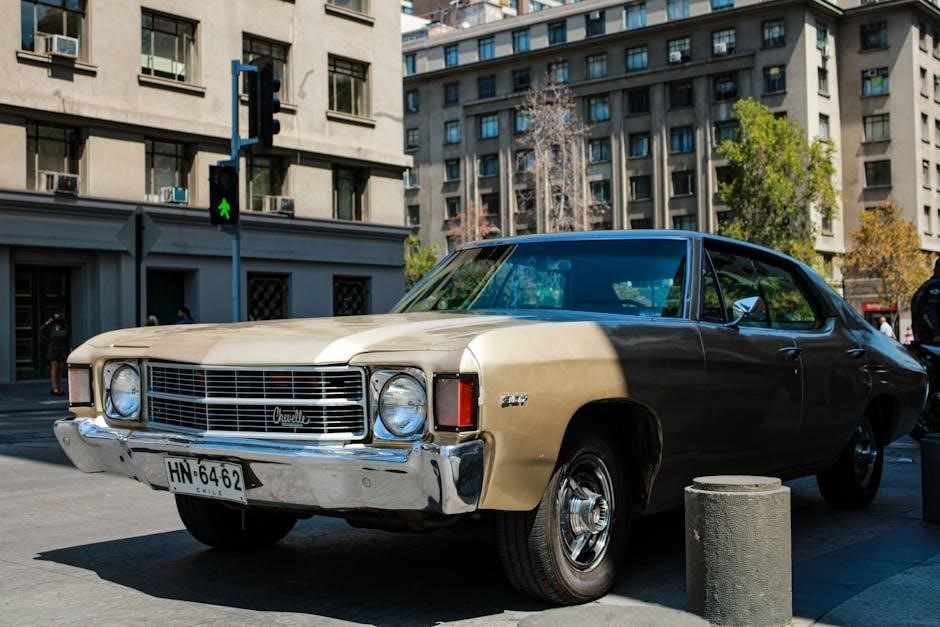
The 1966 Chevrolet Chevelle SS stands as an iconic muscle car, representing a pivotal moment in automotive history. This guide serves as a central resource for owners and restorers seeking authentic PDF documentation. Successfully restoring or maintaining this classic requires access to original factory information, often found within owner’s manuals and repair guides.

This article compiles links and information regarding downloadable PDF versions of these crucial documents. Whether you’re tackling a complete restoration, addressing a specific mechanical issue, or simply seeking to understand your vehicle better, these resources are invaluable. From radio installation details to intricate air conditioning system schematics, we aim to provide a comprehensive pathway to knowledge.

Understanding the nuances of the 1966 Chevelle SS – its various models, engine options, and component layouts – is greatly enhanced by having the original literature at your fingertips. Let’s begin the journey of rediscovering this automotive legend!

Locating the Original 1966 Chevelle SS Owner’s Manual (PDF)

Finding a pristine original 1966 Chevelle SS owner’s manual can be challenging. Fortunately, high-quality PDF versions are available online. Several websites specialize in vintage automotive literature, offering downloadable manuals for a fee or, occasionally, as free resources. A thorough internet search using keywords like “1966 Chevelle SS owner’s manual PDF” will yield numerous results.

Beware of low-resolution scans or incomplete manuals. Look for reputable sources that guarantee a fully functional and readable PDF document. These manuals contain vital information regarding vehicle operation, maintenance schedules, and basic troubleshooting. They are essential for understanding the car’s features and ensuring its longevity.

Digital copies offer the convenience of easy access and portability, allowing you to consult the manual while working on your vehicle. Preserve a copy on multiple devices for safekeeping!

Understanding Chevelle SS Model Variations (1966)

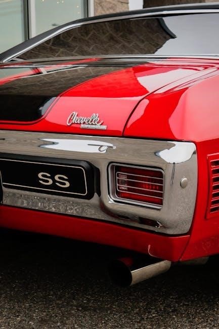
The 1966 Chevelle SS wasn’t a single, unified model; variations existed impacting available options and features. Understanding these nuances is crucial for accurate restoration. The base Chevelle 300 series could be upgraded with the SS package, adding distinct styling cues like a blacked-out grille and simulated air intakes.

Crucially, the SS package didn’t automatically include a high-performance engine. Buyers could choose between the 283, 327, or the potent 396 cubic inch V8. Identifying the original engine is vital when referencing PDF repair manuals.

Furthermore, body styles – coupes, convertibles, and wagons – each had slight differences. PDF documentation often specifies procedures unique to each configuration. Knowing your car’s specific build will ensure you’re using the correct restoration instructions.

Engine Specifications for the 1966 Chevelle SS

Accurate engine identification is paramount when utilizing 1966 Chevelle SS PDF repair manuals. The SS offered three primary engine choices. The standard was a 283 cubic inch V8, but the 327 and the formidable 396 were available. The 396, tested “through a wet set of paces,” was a performance leader.

PDF guides detail specific tuning and maintenance procedures for each engine. Horsepower ratings varied significantly – from around 220hp for the 283 to upwards of 360hp for certain 396 configurations.

Transmission choice (3-speed manual or Powerglide automatic) also impacts engine performance parameters detailed in the manuals. Referencing engine codes and casting numbers, as outlined in PDF resources, confirms original specifications.

396 Cubic Inch Engine Details

PDF repair manuals provide crucial details for the 1966 Chevelle SS’s 396 cubic inch engine. This big-block V8 was a performance highlight, available in various horsepower ratings. PDF guides outline procedures for identifying specific 396 variants based on casting numbers and date codes.

Detailed diagrams within the PDFs illustrate the engine’s internal components, aiding in disassembly and reassembly. Troubleshooting sections address common issues, like carburetor adjustments and valve train noise.

Specific torque specifications for head bolts, main bearing caps, and other critical fasteners are readily available. The manuals also cover procedures for timing adjustment and ignition system maintenance, ensuring optimal performance of this powerful engine.

327 Cubic Inch Engine Details

PDF repair manuals offer comprehensive guidance for servicing the 1966 Chevelle SS’s 327 cubic inch engine. These documents detail the various 327 configurations, from two-barrel to four-barrel setups, and their respective horsepower ratings. PDF diagrams clearly illustrate the engine’s layout, facilitating component identification during rebuilds.

Troubleshooting sections within the manuals address common 327 issues, such as oil leaks, overheating, and poor performance. Detailed instructions cover valve lash adjustment, carburetor tuning, and ignition timing procedures.

Crucially, the PDFs provide precise torque specifications for all engine fasteners, ensuring proper assembly and preventing damage. They also include wiring diagrams for the 327’s electrical system, aiding in diagnosis and repair.

Transmission Options and Manuals

PDF repair manuals for the 1966 Chevelle SS extensively cover available transmission choices. Detailed schematics and exploded views illustrate the 3-speed manual transmission, aiding in disassembly, inspection, and repair. PDF guides provide step-by-step instructions for clutch adjustment and linkage troubleshooting.

Furthermore, these manuals dedicate significant sections to the Powerglide automatic transmission. Troubleshooting flowcharts help diagnose common issues like slipping or harsh shifting. PDF diagrams clarify internal component locations and proper fluid level checks.

Importantly, the manuals include torque specifications for all transmission fasteners, ensuring correct reassembly. They also detail procedures for band adjustment and filter replacement, vital for maintaining optimal performance.

3-Speed Manual Transmission Information

PDF manuals for the 1966 Chevelle SS’s 3-speed manual transmission offer comprehensive repair guidance. Detailed illustrations showcase the gear train, synchronizers, and shift linkage. Troubleshooting sections pinpoint common issues like difficult shifting or gear noise, providing diagnostic steps.

Specifically, the PDFs detail clutch adjustment procedures, ensuring smooth engagement and disengagement. They also cover the inspection and replacement of worn components like throw-out bearings and clutch discs. Torque specifications for all fasteners are clearly listed.

Moreover, these guides include instructions for removing and reinstalling the transmission, along with detailed explanations of the shift linkage adjustment process. Diagrams illustrate proper lubrication points for long-lasting operation.

Powerglide Automatic Transmission Information

PDF repair manuals for the 1966 Chevelle SS’s Powerglide automatic transmission provide detailed overhaul instructions. Diagrams illustrate the internal components, including the planetary gearsets, hydraulic circuits, and valve body assembly. Troubleshooting guides assist in diagnosing common problems like slipping gears or harsh shifting.

Specifically, the PDFs cover fluid level checks, filter replacement procedures, and band adjustment techniques. They also detail the disassembly and reassembly of the transmission, with clear step-by-step instructions. Torque specifications for all components are included.

Furthermore, these guides offer insights into diagnosing and repairing hydraulic leaks, as well as adjusting the transmission linkage for proper operation. Detailed explanations of the Powerglide’s unique features are also provided.

Braking System Overview and Maintenance

PDF manuals for the 1966 Chevelle SS braking system detail the drum brake configuration, including wheel cylinder inspection and replacement. Diagrams illustrate the brake line routing and master cylinder assembly. Maintenance schedules recommend regular inspections for leaks and worn components.

Specifically, the PDFs cover brake shoe replacement procedures, drum turning techniques, and adjusting brake shoe clearance. They also detail the bleeding process to remove air from the hydraulic lines, ensuring optimal stopping power. Troubleshooting guides address common issues like spongy pedals.

Furthermore, these guides offer insights into inspecting and maintaining the emergency brake cable, along with detailed torque specifications for all brake components. Proper adjustment and maintenance are crucial for safe operation.

Suspension System Details

PDF repair manuals for the 1966 Chevelle SS provide detailed schematics of the front and rear suspension systems. Illustrations showcase the coil spring and leaf spring setups, along with shock absorber placement and mounting. Detailed instructions cover inspecting ball joints, tie rod ends, and control arm bushings for wear.

The manuals outline procedures for replacing worn suspension components, including spring removal and installation, and shock absorber replacement. Torque specifications are crucial for ensuring proper assembly and handling. Alignment procedures are also explained, emphasizing the importance of correct wheel angles.

Additionally, the PDFs offer guidance on inspecting and lubricating suspension components, extending their lifespan and maintaining optimal ride quality. Proper maintenance ensures safe and predictable handling characteristics.

Electrical System Guide

PDF manuals for the 1966 Chevelle SS offer comprehensive wiring diagrams, detailing the entire electrical system. These diagrams illustrate the routing of wires for headlights, taillights, turn signals, and the ignition system. Instructions cover testing components like the voltage regulator, alternator, and starter motor.

Troubleshooting guides within the PDFs assist in diagnosing common electrical issues, such as short circuits and open circuits. Detailed steps are provided for replacing fuses, bulbs, and wiring harnesses. Information on the AM radio wiring is also included, aiding in its installation or repair.

Safety precautions are emphasized throughout the electrical system section, warning against working on live circuits. Proper grounding techniques are highlighted to prevent electrical shocks and ensure system functionality.

Interior Components and Installation

PDF guides for the 1966 Chevelle SS provide detailed instructions for interior restoration. Specifically, headliner installation is covered step-by-step, outlining the necessary tools and parts – like part number 99-8276-000. The manuals detail removing existing materials and properly adhering the new headliner.

Regarding the 1966 radio lineup, PDFs offer wiring diagrams for both manual AM options and potentially transistorized models. Instructions clarify connections and mounting procedures. Seat upholstery replacement, dashboard component installation, and door panel attachment are also addressed.

These manuals emphasize proper alignment and securing techniques for all interior parts, ensuring a factory-correct appearance and long-lasting durability. Diagrams illustrate fastener locations and torque specifications.

Headliner Installation Instructions

The 1966 Chevelle SS headliner installation, as detailed in available PDF manuals, begins with removing all factory remnants. Essential tools are specified, alongside the required parts – notably part number 99-8276-000. Instructions emphasize careful removal of window tops to avoid damage.

PDF guides illustrate prepping the roof frame, ensuring a clean and smooth surface for adhesion. Proper adhesive application techniques are outlined, stressing even coverage for a wrinkle-free finish. Alignment is critical; manuals provide visual aids for positioning the headliner correctly.

Securing the headliner around the window frames and roof edges is thoroughly explained, including trim installation. These PDFs offer a step-by-step approach for a professional-quality result.

Radio Installation (AM Manual Options)

Original 1966 Chevelle SS AM radio installation, as found in PDF manuals, details the process for both factory and aftermarket options. The Chevelle’s 1966 radio lineup included a manual AM unit, offering instant music and news. PDF guides illustrate the dashboard disassembly required for access.

Wiring diagrams are crucial, clearly showing connections for power, ground, and the antenna. Manuals emphasize correct polarity to prevent damage. Mounting bracket installation is explained, ensuring a secure fit. Instructions cover antenna cable routing, avoiding interference with other systems.

Testing the radio’s functionality post-installation is a key step, detailed within the PDF resources, guaranteeing optimal performance and a classic listening experience.

Air Conditioning System (Add-On Kits & Instructions)

PDF guides detail installing aftermarket air conditioning in a 1966 Chevelle SS, as factory A/C was not standard. Kits for 1964-67 Chevrolet Chevelles are commonly referenced, containing necessary components. Instructions emphasize careful routing of refrigerant lines, avoiding engine heat and moving parts.

The PDF documentation outlines evaporator and condenser mounting procedures, ensuring proper airflow. Wiring diagrams illustrate connecting the compressor to the vehicle’s electrical system. Vacuum line connections are crucial, detailed in the manuals for proper operation.

Refrigerant charging procedures, along with safety precautions, are highlighted, ensuring a cool and comfortable ride. Detailed diagrams aid in successful installation.

Evaporator and Blower Assembly Removal (Under Hood & Dash)

PDF repair manuals for the 1966 Chevelle SS detail a specific procedure for removing both the under-hood evaporator and the in-dash blower assembly. Factory manuals recommend a systematic approach, starting with disconnecting the electrical connections and refrigerant lines – with proper safety precautions.

The guides illustrate removing the evaporator housing from the engine compartment, noting potential obstructions. Inside the cabin, instructions focus on accessing the blower motor and fan, often requiring partial dashboard disassembly. Detailed diagrams show screw locations and component arrangements.

Careful attention is given to preserving vacuum lines and ductwork. PDFs emphasize labeling components for easier reassembly, ensuring proper airflow and system functionality.

Steering System Information

PDF repair manuals for the 1966 Chevelle SS provide comprehensive details on the steering system, focusing on the manual steering gear box. Diagrams illustrate the components, including the steering wheel, column, and linkage, offering exploded views for clarity.

The guides detail adjustment procedures for minimizing play and ensuring responsive steering. Troubleshooting sections address common issues like hard steering or wandering, with step-by-step diagnostic instructions. PDFs also cover inspection of steering components for wear and damage.

Information on lubrication points and recommended fluids is included, alongside torque specifications for critical fasteners. Detailed instructions aid in the removal and installation of steering components, ensuring proper alignment and functionality.

Manual Steering Gear Box Details

PDF manuals for the 1966 Chevelle SS dedicate sections to the manual steering gear box, outlining its construction and operation. Detailed exploded views illustrate internal components like the worm gear, sector shaft, and ball nut, aiding in understanding its mechanics.

Adjustment procedures are thoroughly explained, focusing on preload and backlash settings to optimize steering feel and minimize wandering. Troubleshooting guides pinpoint common issues like leaks, excessive play, or binding, with diagnostic steps.

PDFs provide torque specifications for mounting bolts and adjusting screws, ensuring proper assembly. Instructions cover removal, disassembly, inspection, and reassembly, including lubrication recommendations for long-term reliability.

Chevrolet Performance Parts & Crate Engine Information

PDF resources for the 1966 Chevelle SS often include catalogs and guides detailing Chevrolet Performance Parts. These documents showcase available crate engines, specifying horsepower, torque, and compatibility with the Chevelle chassis.

Installation instructions for crate engines are frequently provided, covering mounting, wiring, fuel system connections, and exhaust integration. PDFs highlight necessary modifications to the existing vehicle components for a seamless swap.

Performance parts sections detail upgrades for various systems, including carburetors, intakes, cylinder heads, and ignition components. Compatibility charts ensure correct part selection, while technical specifications aid in informed decision-making.

Troubleshooting Common 1966 Chevelle SS Issues

PDF repair manuals dedicated to the 1966 Chevelle SS dedicate sections to diagnosing frequent problems. These guides detail procedures for addressing issues with the engine – including starting difficulties, overheating, and poor performance – alongside transmission slippage or rough shifting.

Electrical system faults, like faulty wiring or dim headlights, are covered with troubleshooting flowcharts and wiring diagrams. Braking system concerns, such as spongy pedals or pulling, receive detailed inspection steps.

PDFs also address suspension noises, steering wander, and air conditioning malfunctions, offering solutions ranging from simple adjustments to component replacements. Detailed illustrations and step-by-step instructions simplify the repair process.

Resources for 1966 Chevelle SS Restoration

Numerous online resources offer PDF downloads of original and reproduction 1966 Chevelle SS materials. Forums dedicated to classic Chevrolet vehicles frequently host shared manuals, wiring diagrams, and parts catalogs in PDF format.

Specialty websites focus on Chevelle restoration, providing curated collections of PDF documents, including factory service manuals, assembly instructions, and technical bulletins. These resources often categorize information by system – engine, transmission, brakes, and interior.

Digital archives and online libraries may contain scanned copies of original owner’s manuals and shop manuals available as PDF files. Utilizing these resources streamlines the restoration process, offering invaluable guidance.

Where to Find PDF Downloads of Repair Manuals

Locating PDF versions of 1966 Chevelle SS repair manuals requires exploring several online avenues. Websites specializing in classic car literature often offer downloadable factory service manuals, sometimes for a fee, ensuring high-quality scans.

Classic car forums dedicated to the Chevelle are excellent sources; members frequently share links to free PDF downloads of repair manuals and related documentation. Online auction sites, like eBay, occasionally list digital copies of original manuals in PDF format.

Chevrolet’s official heritage center and enthusiast clubs may provide access to digitized manuals or direct links to reputable sources offering PDF downloads for restoration projects.

Please read this disclaimer carefully before utilizing any PDF instructions for your 1966 Chevrolet Chevelle SS restoration. These manuals are intended as guides, and mechanical work carries inherent risks. We assume no liability for injury, damage, or incorrect repairs resulting from their use.

Always prioritize safety: disconnect the battery before electrical work, use jack stands when lifting the vehicle, and wear appropriate personal protective equipment. Verify all repairs with a qualified mechanic. Modifications may void warranties and affect vehicle safety.

Information within these PDFs reflects original factory specifications; modern safety standards may differ. Exercise caution and consult current best practices when performing any restoration or repair work.

die hard battery charger instruction manual

Die Hard Battery Charger Instruction Manual: A Comprehensive Guide

Unleash the power! This manual guides you through safely and effectively charging with your Die Hard charger‚ reviving batteries like SpeedKore revives classic muscle.

Welcome to reliable power! Die Hard battery chargers are engineered for dependable performance‚ mirroring the robust build quality seen in vehicles like the carbon-fiber enhanced 1970 Dodge Charger by SpeedKore. These chargers cater to a diverse range of battery types and charging needs‚ from routine maintenance to deep-cycle recovery.

Whether you’re a seasoned mechanic or a first-time user‚ this guide provides comprehensive instructions for safe and efficient operation. Understanding your charger’s capabilities ensures optimal battery health and longevity‚ keeping you powered up and on the move.

Understanding Battery Charger Types

Decoding charging technology! Die Hard offers various charger types to suit different battery needs‚ much like SpeedKore customizes vehicles for peak performance. 12V vs. 6V chargers determine battery voltage compatibility. Smart vs. Traditional chargers differ in automation; smart chargers adjust charging based on battery condition‚ preventing overcharging‚ while traditional chargers offer constant output.

Selecting the correct type is crucial for optimal charging and battery lifespan. This guide will help you identify the best charger for your specific battery type and application‚ ensuring reliable power.

12V vs. 6V Chargers

Voltage matters! 12V chargers are standard for most modern vehicles‚ motorcycles‚ and marine applications – mirroring the power systems in cars like the SpeedKore Dodge Charger. 6V chargers are typically used for older vehicles‚ classic cars‚ and some specialized equipment. Using the incorrect voltage can severely damage your battery.

Always verify your battery’s voltage before connecting a charger. Die Hard chargers are clearly labeled with their voltage compatibility. Incorrect voltage application voids warranties and poses a safety risk.

Smart vs. Traditional Chargers

Intelligence in charging! Traditional chargers deliver a constant voltage and amperage‚ requiring manual monitoring to prevent overcharging – a risky approach‚ much like neglecting a classic car’s maintenance. Smart chargers‚ like many Die Hard models‚ utilize advanced algorithms to automatically adjust charging parameters.

They detect battery state‚ optimize charging speed‚ and prevent overcharging‚ mirroring the precision of SpeedKore’s carbon fiber work. Smart chargers offer features like trickle charging and desulfation for enhanced battery life.

Safety Precautions Before Use

Prioritize safety! Before connecting your Die Hard charger‚ ensure a well-ventilated area‚ free from flammable materials – akin to a meticulously prepared SpeedKore workshop. Always wear safety glasses and gloves to protect against acid splashes and sparks. Never charge a frozen battery; it could explode.

Disconnect the battery from the vehicle to prevent electrical shorts. Inspect the charger cord for damage before each use. Improper use can lead to fire or injury‚ so read this manual thoroughly.

Personal Safety Gear

Protect yourself! When working with batteries and chargers‚ like the precision demanded by SpeedKore’s carbon fiber work‚ appropriate personal protective equipment (PPE) is crucial. Always wear chemical-resistant gloves to shield your hands from battery acid. Safety glasses or a face shield are essential to prevent splashes from reaching your eyes.

Closed-toe shoes are recommended. Avoid wearing metallic jewelry that could create a short circuit. Keep a source of clean water nearby for immediate rinsing in case of acid contact.

Battery Safety Guidelines

Handle with care! Batteries contain corrosive acid and can produce explosive gases – treat them with respect‚ mirroring the meticulous build quality of a SpeedKore Charger. Ensure adequate ventilation during charging to dissipate hydrogen gas. Never smoke or introduce open flames near a charging battery.

Avoid dropping or damaging batteries. If acid spills‚ neutralize it with baking soda and water. Properly dispose of old batteries according to local regulations.

Identifying Your Die Hard Charger Model

Know your tool! Just as enthusiasts identify every detail of a SpeedKore Ghost Charger‚ knowing your Die Hard model is crucial. Locate the model number typically on a sticker affixed to the charger’s casing – often on the back or bottom. This number unlocks specific features and charging profiles.

Refer to this manual or the Die Hard website using the model number to understand your charger’s capabilities and ensure optimal battery care.

Model Number Location

Find the key! Similar to identifying a unique vehicle like the SpeedKore Dodge Charger‚ your Die Hard charger’s model number is its identifier. Typically‚ it’s found on a sticker located on the rear panel or the underside of the unit. Look for a label clearly marked “Model No.” or “Model Number.”

If you can’t find it there‚ check the original packaging or your purchase receipt. This number is vital for accessing specific instructions and support.

Charger Features by Model

Unlock the potential! Just as SpeedKore customizes each Charger‚ Die Hard offers varied features. Basic models provide standard charging‚ while advanced units boast smart charging‚ desulfation‚ and multiple voltage settings. Some include automatic voltage detection‚ simplifying the process.

Higher-end models may feature digital displays‚ temperature compensation‚ and reverse polarity protection. Refer to your model’s specific documentation to fully understand its capabilities and optimize battery performance.

Setting Up Your Die Hard Charger

Prepare for power! Before connecting‚ ensure the charger is on a stable‚ dry surface‚ mirroring the meticulous build of a SpeedKore vehicle. Plug the charger into a grounded AC outlet‚ verifying correct voltage.

Next‚ connect the clamps to the battery terminals – red to positive (+)‚ black to negative (-). A secure connection is vital for efficient charging and preventing sparks. Double-check polarity before proceeding!

Connecting to a Power Source

Power up safely! Your Die Hard charger requires a standard 120V AC outlet. Ensure the outlet is properly grounded‚ much like the chassis of a meticulously restored Dodge Charger. Inspect the power cord for any damage – fraying or exposed wires – before plugging it in.

Avoid using extension cords if possible; if necessary‚ use a heavy-duty cord rated for at least the charger’s amperage.

Connecting to the Battery – Correct Polarity

Critical connection! Always connect the charger clamps to the battery terminals with the correct polarity. Red clamp to positive (+)‚ and black clamp to negative (-). Reversing polarity can severely damage both the charger and the battery‚ similar to a misaligned carbon fiber panel.

Double-check before initiating the charge; a secure connection is vital for efficient and safe charging.

Charging Procedures: Step-by-Step

Initiate the charge! First‚ ensure correct polarity (red to positive‚ black to negative). Select the appropriate charging mode – Standard for routine charging‚ Fast for quicker boosts (if available)‚ or Trickle for maintenance‚ much like fine-tuning a SpeedKore build.

Monitor the charger’s indicators; allow the full cycle to complete for optimal battery health. Disconnect clamps after charging is finished.

Standard Charging Mode

The reliable choice! Standard charging delivers a consistent‚ controlled current‚ ideal for routine battery maintenance – akin to the meticulous craftsmanship of SpeedKore’s carbon fiber work. This mode gently replenishes battery capacity without risking overcharging.

It’s suitable for most lead-acid batteries and provides a balanced charge‚ extending battery lifespan. Monitor the charger’s progress and allow the full cycle to complete for best results.

Fast Charging Mode (If Applicable)

Need a quick boost? If your Die Hard charger features fast charging‚ it delivers a higher current for quicker replenishment – mirroring the speed with which SpeedKore transforms a Dodge Charger. However‚ use this mode cautiously!

It’s best for batteries with significant discharge and should be monitored closely to prevent overheating or damage. Once the battery reaches approximately 80% capacity‚ switch to standard or trickle mode.

Trickle Charging Mode

Maintaining peak performance! Trickle charging provides a low‚ sustained current‚ ideal for maintaining a fully charged battery over extended periods – much like preserving a beautifully restored classic car‚ akin to SpeedKore’s work.

This prevents sulfation and keeps your battery ready for use. It’s perfect for seasonal vehicles or batteries not used frequently. Avoid using trickle charge on severely discharged batteries; begin with standard charging first.

Understanding Charger Indicators & Lights

Decoding the signals! Your Die Hard charger utilizes a system of LEDs and potentially audible alerts to communicate its charging status – similar to how a meticulously crafted car‚ like SpeedKore’s Charger‚ signals quality.

Solid lights typically indicate a specific stage‚ while flashing lights signal issues or progress. Refer to your model’s specific guide to interpret each signal accurately‚ ensuring optimal battery care and preventing damage.

LED Display Meanings

Interpreting the glow! A solid green LED generally signifies a fully charged battery‚ ready for action – much like the polished finish on a SpeedKore creation. Red often indicates charging in progress‚ while a flashing red light may signal a problem‚ like reversed polarity.

Yellow could mean a low voltage or desulfation mode is active. Always consult your charger’s specific documentation for precise interpretations‚ ensuring safe and effective battery maintenance.

Audible Alerts & Their Significance

Listen closely! A single beep often confirms a successful connection‚ similar to the satisfying roar of a restored muscle car like the Dodge Charger from SpeedKore. Continuous beeping usually indicates an error – perhaps reversed polarity or a faulty connection.

A rapid series of beeps could signal overheating. Refer to your manual for specific alert patterns and their meanings‚ prioritizing safety during the charging process.

Troubleshooting Common Issues

Don’t despair! If your charger fails to power on‚ check the power source and ensure the cable is securely connected – much like verifying every carbon fiber component on a SpeedKore Charger. A battery not charging could indicate reversed polarity or a deeply discharged cell.

Overheating? Disconnect immediately! Consult the manual; proper ventilation is key. These steps will get you back on the road.

Charger Won’t Turn On

Powerless? Let’s diagnose! First‚ verify the AC power outlet is functioning correctly – test with another device. Next‚ inspect the charger’s power cord for any visible damage‚ similar to scrutinizing the carbon fiber build of a SpeedKore Dodge Charger. Ensure the cord is firmly plugged into both the charger and the outlet.

If still no power‚ check the internal fuse (if applicable) and consult the warranty information.

Battery Not Charging

Stalled progress? Confirm the battery connections are clean and secure – corrosion hinders charge flow‚ much like imperfections detract from a SpeedKore’s flawless finish. Double-check the polarity; reversed connections prevent charging and can damage the charger or battery.

Verify the charger’s voltage setting matches the battery’s voltage (6V or 12V). A deeply discharged battery may take time to register a charge.

Overheating Issues

Feeling the heat? Excessive heat indicates a problem – immediately disconnect the charger! Poor ventilation‚ like a confined engine bay‚ can cause overheating. Ensure the charger has ample space for airflow. A failing internal component‚ similar to stress fractures in a classic car’s chassis‚ could be the culprit.

Do not operate the charger near flammable materials. Contact support if overheating persists after verifying ventilation.

Maintaining Your Die Hard Charger

Keep it pristine! Regular maintenance ensures longevity‚ much like caring for a restored muscle car. Disconnect the charger before cleaning; use a damp cloth‚ avoiding harsh chemicals. Inspect cables for cracks or fraying – damaged cords are a safety hazard. Store the charger in a cool‚ dry place‚ protected from dust and extreme temperatures.

Proper storage prevents corrosion and ensures reliable performance for years to come.

Cleaning and Storage

Preserve its performance! Always disconnect the charger from both the power source and the battery before any cleaning. Wipe the exterior with a slightly damp cloth; avoid immersing it in water. For stubborn grime‚ a mild soap solution is acceptable‚ but ensure it’s thoroughly dried afterward.

Store in a dry‚ cool environment‚ away from direct sunlight and extreme temperatures‚ similar to protecting a classic car’s finish.

Cable Inspection and Care

Protect the connection! Regularly inspect the charging cables for cracks‚ fraying‚ or exposed wires – damage compromises safety and charging efficiency. Avoid kinking or sharply bending the cables during use or storage‚ much like careful handling of a SpeedKore carbon fiber component.

If damage is found‚ immediately discontinue use and replace the cables. Proper cable care ensures a reliable power flow to your battery.

Battery Types Compatible with Die Hard Chargers

Powering diverse needs! Die Hard chargers are primarily designed for lead-acid batteries – flooded‚ Absorbed Glass Mat (AGM)‚ and Gel cell types. These are common in vehicles and various applications‚ mirroring the broad appeal of a restored 1970 Dodge Charger.

Compatibility with Lithium-Ion batteries varies by model; always check your charger’s specifications before use to avoid damage or safety hazards.

Lead-Acid Batteries (Flooded‚ AGM‚ Gel)

Traditional powerhouses! Flooded lead-acid batteries‚ the oldest type‚ require regular maintenance. AGM (Absorbed Glass Mat) and Gel batteries are sealed and maintenance-free‚ offering convenience. Like the carbon fiber build of SpeedKore’s Ghost Charger‚ these technologies enhance performance.

Die Hard chargers effectively charge all three‚ but selecting the correct mode optimizes charging and extends battery lifespan. Always consult your battery’s specifications.

Lithium-Ion Battery Compatibility (If Applicable)

Modern energy storage! Some newer Die Hard chargers may support Lithium-Ion (Li-ion) batteries‚ commonly found in power tools and some vehicles. Caution: Li-ion charging requires specific voltage and current profiles. Using incorrect settings can cause damage or pose a safety hazard – akin to a poorly built muscle car.

Check your charger’s specifications carefully. If Li-ion charging is supported‚ a dedicated mode will be available. Otherwise‚ do not attempt to charge these batteries.

Desulfation Mode: Reviving Old Batteries

Bring them back to life! Over time‚ lead-acid batteries develop sulfation – a buildup of lead sulfate crystals that reduces capacity‚ much like rust on a classic Charger. Desulfation mode applies a controlled electrical pulse to break down these crystals‚ restoring some of the battery’s original performance.

Use this mode cautiously and only on batteries that aren’t severely damaged. It’s a revival attempt‚ not a miracle cure!

How Desulfation Works

The science of revival! Desulfation utilizes high-frequency‚ low-voltage pulses to gently disrupt the lead sulfate crystals forming on the battery plates. These pulses don’t force current through the battery‚ but rather vibrate the crystals‚ breaking them down into smaller‚ more manageable particles.

This process allows the electrolyte to reach more of the lead surface‚ improving conductivity and restoring lost capacity – a bit like restoring a classic car’s shine!

When to Use Desulfation Mode

Revive‚ don’t replace! Employ desulfation mode on batteries exhibiting reduced performance‚ like a neglected muscle car needing restoration. It’s ideal for batteries that have been deeply discharged or stored for extended periods‚ showing signs of sulfation – slow charging or reduced capacity.

However‚ avoid using it on healthy batteries; focus on those needing a second chance at peak performance‚ mirroring the spirit of SpeedKore’s restorations.

Automatic Voltage Detection Explained

Smart charging simplified! Your Die Hard charger’s automatic voltage detection intelligently identifies your battery’s voltage – 12V or 6V – eliminating manual settings. Like a skilled mechanic diagnosing an engine‚ it ensures the correct charging profile is applied for optimal results.

This feature prevents overcharging or undercharging‚ maximizing battery life and performance‚ much like SpeedKore’s precision engineering.

Reverse Polarity Protection Features

Safeguarding your setup! Die Hard chargers incorporate robust reverse polarity protection. Should you accidentally connect the clamps incorrectly – positive to negative – the charger won’t initiate‚ preventing damage to both the unit and your battery.

This crucial safety net‚ akin to the reinforced chassis of a SpeedKore Charger‚ shields against potentially costly mistakes‚ ensuring a worry-free charging experience.

Understanding Charging Amperage

Power delivery explained! Amperage dictates the charging speed; higher amperage means faster charging‚ but isn’t always ideal. Smaller batteries require lower amperage to avoid overheating‚ much like carefully tuning a high-performance engine like those found in SpeedKore builds.

Consult your battery’s specifications. Using excessive amperage can shorten its lifespan‚ while too little extends charging time unnecessarily.

Choosing the Right Amperage for Your Battery

Match the power! Generally‚ a charging rate of 10-15% of the battery’s amp-hour (Ah) rating is recommended. For example‚ a 100Ah battery ideally charges at 10-15 amps – a balanced approach‚ similar to SpeedKore’s carbon fiber builds.

Refer to your battery’s label or manual. Some batteries‚ like AGM or Gel‚ have specific amperage recommendations. Always prioritize these guidelines to maximize battery life and performance.

Die Hard Charger Specifications (Common Models)

Power details! The Die Hard DX4 is a 2/10/50 amp charger‚ suitable for various vehicles – akin to the versatile 1970 Dodge Charger reimagined by SpeedKore. The DR15 is a 15 amp‚ 12V maintainer‚ perfect for long-term storage.

The DH20 is a 20 amp charger‚ offering faster charging capabilities. Always check the model number on your charger for precise specifications and compatibility. Refer to the Die Hard website for the latest model details.

Warranty Information and Support

Peace of mind! Die Hard chargers typically come with a one-year limited warranty covering manufacturing defects‚ ensuring reliability like SpeedKore’s carbon fiber builds. Proof of purchase is required for all warranty claims.

For support‚ visit the official Die Hard website or contact their customer service line. Online resources‚ including FAQs and troubleshooting guides‚ are readily available. Retain this manual for warranty reference and future assistance.

Frequently Asked Questions (FAQ)

Quick answers! Q: Can I charge a completely dead battery? A: Yes‚ but desulfation mode (if equipped) may be needed‚ similar to reviving a classic Charger. Q: What if the charger won’t turn on? A: Check the power source and cable connections.

Q: Is this charger safe for all battery types? A: Refer to the compatibility section. Q: How long does charging take? A: It varies based on battery condition and charger mode.

Resources and Further Information

Expand your knowledge! For detailed support and the latest updates on your Die Hard charger‚ visit the official Die Hard Website & Support page. Explore comprehensive battery information and standards at the Battery Council International (BCI) Resources website.

Discover insights into automotive restoration‚ much like SpeedKore’s Charger builds‚ and battery maintenance best practices. These resources will empower you to maximize your charger’s performance and battery lifespan.

Die Hard Website & Support

Need assistance? The official Die Hard website is your primary resource for troubleshooting‚ FAQs‚ and accessing downloadable manuals – ensuring your charging experience is smooth‚ like a restored SpeedKore Charger.

Find detailed product specifications‚ warranty claim submissions‚ and contact information for dedicated support specialists. Explore helpful videos demonstrating proper charging techniques and safety protocols. Register your charger for exclusive updates and promotions!

Battery Council International (BCI) Resources

Expand your knowledge! The Battery Council International (BCI) offers invaluable resources for understanding battery technology and maintenance – crucial for maximizing your Die Hard charger’s performance‚ much like understanding the carbon fiber in a SpeedKore build.

Access industry standards‚ technical documents‚ and educational materials covering battery types‚ safety guidelines‚ and proper charging practices. BCI’s website provides a wealth of information for both beginners and experienced users seeking a deeper understanding of battery power.

keurig mini instructions

Keurig Mini Instructions: A Comprehensive Guide

This comprehensive guide offers detailed Keurig K-Mini instructions, including setup, operation, maintenance, and troubleshooting, utilizing available manuals and resources in PDF format.

Access user manuals, video tutorials, and answers to frequently asked questions to maximize your single-serve coffee experience with your Keurig K-Mini coffee maker;

The Keurig K-Mini is a compact, single-serve coffee maker designed for convenience and space-saving functionality. It’s an ideal choice for small kitchens, dorm rooms, or anyone seeking a quick and easy brewing solution. This model simplifies the coffee-making process, delivering a fresh cup with minimal effort.

Unlike larger Keurig models, the K-Mini prioritizes portability and simplicity. It brews one cup at a time, reducing waste and ensuring a consistently fresh taste. Users can find detailed instructions and care guides available online, often in PDF format, to help them understand all features.

This guide will walk you through every step, from initial setup and operation to maintenance and troubleshooting, ensuring you get the most out of your K-Mini. Resources like keurig.ca provide helpful video instructions, complementing the written manuals for a complete learning experience.

Unboxing and Initial Setup

Upon unboxing your Keurig K-Mini, carefully remove all packaging materials. Verify that all components are present, referencing the included documentation or online resources like the user manual available as a PDF. Before first use, it’s crucial to perform a thorough cleaning cycle.

Fill the water reservoir with fresh, filtered water to the maximum fill line. Plug the K-Mini into a grounded electrical outlet. To initiate the initial setup, run a few brewing cycles without a K-Cup pod. This helps flush out any residual manufacturing debris and primes the system.

Consult the user guide for specific instructions on this process; many guides offer video demonstrations on keurig.ca. Discard the water from each cycle. This initial setup ensures optimal performance and a cleaner, better-tasting first cup of coffee.

Component Identification

The Keurig K-Mini consists of several key components essential for operation. The Water Reservoir, typically removable, holds the water supply for brewing. The K-Cup Pod Holder securely accommodates single-use K-Cup pods, facilitating the brewing process. It’s designed for easy pod insertion and removal.

The Power Cord & Base provide electrical connection and stable support for the unit. Familiarize yourself with the location of the power button and indicator lights. The exterior housing protects internal components and features a sleek, compact design.

Refer to your user manual (available as a PDF) for a detailed diagram identifying each part. Understanding these components is crucial for proper use, maintenance, and troubleshooting, ensuring a seamless coffee brewing experience with your K-Mini.

Water Reservoir

The Keurig K-Mini’s Water Reservoir is a removable component designed for convenient filling and cleaning. It’s crucial to use fresh, filtered water for optimal brewing quality and to minimize scale buildup. The reservoir has a maximum capacity, indicated in the manual and on the reservoir itself – typically around 12 ounces.

Ensure the reservoir is securely seated in its designated slot before each brew cycle. Proper placement is essential to prevent leaks and ensure correct water flow. Regularly inspect the reservoir for any cracks or damage, and replace if necessary.

Cleaning the reservoir is vital; refer to the user guide (available as a PDF) for specific instructions. Avoid using abrasive cleaners, as they can damage the plastic. Maintaining a clean reservoir contributes to the longevity and performance of your K-Mini.

K-Cup Pod Holder

The K-Cup Pod Holder is a central component of the Keurig K-Mini, designed to securely hold the single-serve coffee pod during the brewing process. It features an entrance needle that pierces the top of the pod and an exit needle that allows the brewed coffee to flow into your cup.

Regular cleaning of the pod holder is essential to prevent clogging and ensure optimal coffee flavor. The manual (available in PDF format) provides detailed instructions on how to remove and clean the pod holder. Pay close attention to the entrance and exit needles, as coffee grounds can accumulate there.

Ensure the pod holder is properly aligned and securely fastened before each brew. Using a compatible K-Cup pod or a reusable filter (like the My K-Cup) is crucial for proper operation. Inspect the pod holder for any damage or cracks regularly.

Power Cord & Base

The Keurig K-Mini’s power cord and base are fundamental for operation, providing the electrical connection and stable foundation for the brewer. Always ensure the power cord is securely plugged into a grounded electrical outlet. Refer to the safety precautions in the user manual (available as a PDF) regarding electrical safety.

The base houses the heating element and internal components. Avoid immersing the base in water or any other liquid. Regularly inspect the power cord for any signs of damage, such as fraying or exposed wires. If damage is detected, discontinue use immediately.

Proper placement of the K-Mini on a stable, level surface is crucial for safe operation. The base should remain dry and free from obstructions. The manual details troubleshooting steps if the unit fails to power on.

Operating Your Keurig Mini

This section details the simple steps for brewing with your K-Mini, covering water reservoir filling, K-Cup insertion, brew size selection, and initiating the brew cycle.

Filling the Water Reservoir

The Keurig K-Mini features a removable water reservoir, designed for convenient filling and easy cleaning. To begin, gently lift the reservoir straight up from the brewer, ensuring no water spills. Locate the maximum fill line indicated inside the reservoir – do not exceed this level to prevent overflow during brewing.

Fill the reservoir with fresh, filtered water to your desired level. Using filtered water is highly recommended to optimize the taste of your coffee and minimize scale buildup within the machine. Once filled, carefully slide the reservoir back down onto the brewer, ensuring it clicks securely into place. The K-Mini is now ready for brewing, with water available for creating your perfect single cup!

Regularly checking and refilling the reservoir ensures consistent brewing performance and prevents interruptions during your coffee routine.

Inserting a K-Cup Pod

Before brewing, lift the handle on the K-Mini to open the K-Cup pod holder. This reveals the space where your chosen K-Cup pod will be inserted. Carefully remove the foil lid from the K-Cup pod – this is essential for proper brewing. Then, gently place the K-Cup pod into the holder, ensuring it sits flat and is properly seated.

Close the handle firmly until it clicks shut, securing the K-Cup pod in place. This action pierces the pod, preparing it for the brewing process. It’s important to ensure the handle is fully closed to prevent leaks or brewing issues. The K-Mini is now ready to extract the delicious flavors from your selected K-Cup pod!

Always dispose of used K-Cup pods responsibly after brewing.

Brewing a Single Cup

With the K-Cup pod securely in place, your Keurig Mini is ready to brew a perfect single cup. Place a mug or cup on the drip tray to catch the freshly brewed coffee. Press the brew button to initiate the brewing cycle. The Keurig Mini will automatically draw water from the reservoir and brew directly into your cup.

The brewing process takes only a few moments. Pay attention to the indicator lights, which will signal when brewing is in progress and when it’s complete. Once finished, carefully remove your mug, being mindful of the hot coffee.

Enjoy your freshly brewed beverage! Remember to lift the handle to safely remove the used K-Cup pod.

Selecting Brew Size

The Keurig Mini offers a streamlined brewing experience, typically featuring a single brew size option for a standard 6-ounce cup. Unlike some larger Keurig models, the K-Mini doesn’t usually have multiple size selections. This simplicity makes operation quick and easy, perfect for a single serving of coffee, tea, or hot cocoa.

Before initiating the brew cycle, ensure your mug is appropriately sized to accommodate the 6-ounce output. Using a larger mug will prevent spills, while a smaller one might overflow. The K-Mini is designed for convenience, delivering a consistent brew volume with each use.

This focused approach to brew size contributes to the compact design and user-friendly nature of the Keurig Mini.

Starting the Brew Cycle

Once the water reservoir is filled and a K-Cup pod is correctly inserted, initiating the brew cycle on your Keurig Mini is straightforward. Simply press the brew button – typically a single, prominent button on the top of the unit. The indicator light will illuminate, signaling that the brewing process has begun.

The Keurig Mini will automatically pierce the K-Cup pod and pump hot water through it, delivering your beverage directly into your mug. The brewing process usually takes less than a minute, providing a quick and convenient coffee experience.

Remain patient during brewing and avoid lifting the handle until the cycle is complete. The machine will automatically stop when finished, and the indicator light will turn off.

Maintenance and Cleaning

Regular maintenance ensures optimal performance and longevity of your Keurig Mini. Cleaning includes descaling, exterior wiping, and needle/pod holder sanitation.

Descaling the Keurig Mini

Descaling your Keurig Mini is crucial for removing mineral buildup, ensuring optimal brewing performance and extending the lifespan of your appliance. Over time, minerals from water can accumulate, affecting the taste of your coffee and potentially damaging the internal components.

The descaling process typically involves running a descaling solution – often a mixture of white vinegar and water, or a commercially available descaling product – through the brewer. Follow the specific instructions provided with your descaling solution or refer to the Keurig Mini user manual for precise ratios and procedures.

Generally, you’ll fill the reservoir with the descaling solution, run a full brew cycle without a K-Cup pod, and then repeat with fresh water several times to rinse away any remaining solution. Regular descaling, typically every 3-6 months depending on water hardness, will keep your Keurig Mini functioning at its best and delivering delicious coffee.

Cleaning the Exterior

Maintaining a clean exterior for your Keurig Mini not only enhances its appearance but also contributes to overall hygiene. Regularly wiping down the exterior surfaces with a soft, damp cloth is recommended. Avoid using abrasive cleaners or scouring pads, as these can damage the finish.

Pay particular attention to areas prone to spills or coffee residue, such as around the K-Cup pod holder and the drip tray. For stubborn stains, a mild dish soap solution can be used, followed by a thorough rinsing with clean water. Ensure the appliance is unplugged before cleaning.

Keeping the exterior clean prevents buildup and maintains a fresh look for your Keurig Mini. Consistent cleaning, combined with internal maintenance, ensures a pleasant and sanitary coffee brewing experience. Refer to the user manual for specific cleaning recommendations.

Cleaning the K-Cup Pod Holder

Regularly cleaning the K-Cup pod holder is crucial for optimal Keurig Mini performance and coffee flavor. After each use, remove the pod holder and discard the used K-Cup pod. Rinse the pod holder thoroughly with warm water to remove any coffee grounds or residue.

For a deeper clean, the pod holder can be disassembled (if applicable, consult your manual) and washed with mild dish soap. Pay close attention to the needle piercing points, ensuring they are free from obstructions. A small brush or toothpick can be helpful for this. Rinse completely and allow to air dry before reassembling.

A clean K-Cup pod holder prevents clogging and ensures proper water flow during brewing. Consistent cleaning contributes to a better tasting cup of coffee and extends the life of your Keurig Mini.

Cleaning the Entrance and Exit Needles

Maintaining clean entrance and exit needles is vital for a consistently great brew from your Keurig Mini. Over time, coffee oils and fine grounds can clog these needles, impacting water flow and coffee quality. Refer to keurig.ca for helpful video instructions demonstrating the cleaning process.

To clean, carefully remove the K-Cup pod holder. Locate the entrance needle (pierces the top of the K-Cup) and the exit needle (pierces the bottom). Use a paperclip or a Keurig needle cleaning tool to gently dislodge any debris. Be extremely cautious to avoid bending or damaging the needles.

Flush the Keurig Mini by running a brew cycle with only water to clear any loosened particles. Regular needle cleaning prevents slow brewing and ensures optimal flavor extraction.

Troubleshooting Common Issues

Common problems like the Keurig Mini not powering on, heating, or leaking are addressed with solutions found in user manuals and online resources.

Keurig Mini Not Turning On

If your Keurig Mini fails to power on, begin by verifying the power cord is securely connected to both the appliance and a functioning electrical outlet.

Test the outlet with another device to confirm it’s delivering power. Inspect the power cord for any visible damage, such as fraying or cuts, and replace it if necessary. Ensure the Keurig Mini is properly seated on its base; sometimes, a loose connection can prevent it from turning on.

Occasionally, a simple reset can resolve the issue. Unplug the Keurig Mini from the outlet, wait approximately 60 seconds, and then plug it back in. If the problem persists, consult the user manual for specific troubleshooting steps or contact Keurig customer support for further assistance. A blown internal fuse is a less common, but possible, cause.

Water Not Heating

If your Keurig Mini isn’t heating water, the most common culprit is scale buildup. Descaling the machine regularly is crucial for optimal performance. Refer to the ‘Descaling the Keurig Mini’ section of this guide for detailed instructions on how to properly descale your appliance.

Ensure the water reservoir is filled to the minimum fill line, as the heating element may not function correctly with insufficient water. Verify that the Keurig Mini is fully plugged in and receiving power. A faulty heating element is a less frequent cause, potentially requiring professional repair or replacement.

Run a few brewing cycles with just water (no K-Cup) to help flush out any potential blockages. If the issue continues, consult the Keurig user manual or contact customer support for further troubleshooting.

Coffee Brewing Too Slowly

Slow brewing with your Keurig Mini often indicates a blockage within the internal components. Scale buildup is a primary cause, restricting water flow. Thoroughly descaling the machine, as detailed in the ‘Descaling the Keurig Mini’ section, is the first step to address this issue.

Inspect the entrance and exit needles for coffee grounds or mineral deposits. Carefully clean these needles following the instructions in the ‘Cleaning the Entrance and Exit Needles’ section. A clogged K-Cup pod holder can also contribute to slow brewing; ensure it’s free of debris.

If the problem persists, try using a different K-Cup pod to rule out a pod-specific issue. Regularly cleaning your Keurig Mini will prevent future slowdowns and maintain optimal brewing speed.

Leaking Issues

Leaking from your Keurig Mini can stem from several sources. First, verify the water reservoir is correctly seated and not overfilled. Ensure it’s properly aligned with the machine’s base to create a secure seal. Inspect the reservoir for any cracks or damage, replacing it if necessary.

Check the K-Cup pod holder assembly for proper installation and sealing. A loose or damaged pod holder can cause leaks during the brewing process. Examine the entrance and exit needles for blockages or damage that might disrupt the water flow and lead to leakage.

If leaks continue, carefully inspect the area around the water pump and internal tubing for any visible signs of damage. Consistent cleaning and descaling, as outlined in the maintenance sections, can help prevent leaks caused by mineral buildup.

Advanced Features & Tips

Explore features like the My K-Cup reusable filter, travel mug compatibility, energy-saving mode, and understand indicator lights for optimal Keurig Mini performance.

Using My K-Cup Universal Reusable Filter

The My K-Cup Universal Reusable Filter expands your brewing options beyond pre-packaged K-Cup pods, allowing you to enjoy your favorite ground coffee with your Keurig Mini.

To use it, simply fill the filter with your desired amount of ground coffee – typically one to two tablespoons, adjusting to your taste preference. Ensure the coffee is ground to a medium consistency for optimal brewing.

Securely close the filter lid and insert the filled My K-Cup into the K-Cup pod holder as you would a standard pod. Brew as usual, selecting your preferred cup size. Remember to thoroughly clean the reusable filter after each use to prevent buildup and maintain coffee quality. Regular cleaning ensures consistent flavor and prolongs the filter’s lifespan, offering a sustainable and cost-effective alternative to single-use pods;

This accessory unlocks a world of coffee choices for your Keurig Mini!

Travel Mug Compatibility

The Keurig Mini, despite its compact size, offers compatibility with a variety of travel mugs, allowing you to enjoy your freshly brewed coffee on the go. However, due to the limited space under the dispenser, it’s crucial to select a travel mug with appropriate dimensions.

Ensure the mug’s height, when placed on the drip tray, doesn’t exceed the clearance under the dispenser. Mugs with a diameter that fits comfortably within the pod holder area are also recommended. Removing the drip tray can provide additional height for taller mugs.

Always exercise caution when using travel mugs, as they may be hotter to the touch than a standard Keurig cup. Verify the mug is stable and secure on the base before initiating the brew cycle to prevent spills. Experiment with different mugs to find the perfect fit for your Keurig Mini and your lifestyle!

Energy Saving Mode

The Keurig Mini is equipped with an automatic energy-saving mode designed to conserve electricity and reduce environmental impact. After a period of inactivity, typically around five minutes, the brewer automatically enters a low-power standby state.

In this mode, the internal heating element is deactivated, significantly reducing energy consumption. The indicator lights will remain illuminated to signal the brewer is still powered on, but ready to brew with minimal energy use.

To resume brewing, simply press any button on the Keurig Mini. The brewer will quickly reheat the water, preparing it for your next cup. This feature contributes to a more sustainable and cost-effective coffee brewing experience, without compromising convenience or speed.

Understanding Indicator Lights

The Keurig Mini utilizes indicator lights to communicate its operational status, providing clear visual cues for the user. A solid power light indicates the brewer is on and ready. During the brewing process, the light will typically flash, signaling active heating and water dispensing.

If the light flashes rapidly or a different color appears (depending on the model), it may indicate a problem, such as a need for descaling or a water reservoir issue. Refer to the troubleshooting section of your user manual for specific error codes.

The lights also confirm when the brewer has reached optimal brewing temperature. Understanding these signals ensures efficient operation and helps maintain the longevity of your Keurig Mini, allowing for a consistently perfect cup of coffee.

Safety Precautions

Always prioritize electrical safety and be mindful of hot surfaces during operation. Follow proper usage guidelines to prevent burns and ensure safe, enjoyable brewing experiences.

Electrical Safety

To ensure safe operation of your Keurig Mini, always plug the appliance into a grounded electrical outlet. Never operate the Keurig with a damaged cord or plug; if damaged, it should be serviced by a qualified technician. Avoid using extension cords, as they can pose a safety hazard.

Do not immerse the Keurig Mini base in water or any other liquid. Unplug the appliance when not in use and before cleaning. Keep the cord away from hot surfaces. Never attempt to disassemble or repair the Keurig Mini yourself, as this could result in electric shock or injury. Ensure the voltage of your outlet matches the voltage specified on the appliance’s rating label. Regularly inspect the power cord for any signs of wear or damage, and replace it if necessary. Following these precautions will help prevent electrical hazards and ensure safe operation.

Hot Surface Warnings

The Keurig Mini utilizes hot water and heated components during operation, presenting potential burn hazards. Exercise extreme caution when handling the appliance, particularly during and immediately after brewing. Avoid touching the exterior surfaces, especially around the brew head and water reservoir, as these areas become very hot.

Keep children and pets away from the Keurig Mini during operation to prevent accidental burns. Allow the appliance to cool down completely before attempting to clean or move it. Use caution when opening the K-Cup pod holder after brewing, as steam and hot water may be present. Never touch the entrance or exit needles immediately after use. Be mindful of hot coffee dispensed from the brewer and handle your cup with care. Always prioritize safety and prevent contact with hot surfaces to avoid injury.

Proper Usage Guidelines

To ensure optimal performance and longevity of your Keurig Mini, adhere to these guidelines. Only use potable water in the reservoir, avoiding flavored or carbonated beverages. Utilize K-Cup pods specifically designed for Keurig brewers. Never attempt to brew without a pod inserted, as this can damage the machine. Regularly descale the unit to prevent mineral buildup, following the instructions in the manual.

Do not overfill the water reservoir. Ensure the appliance is placed on a stable, level surface. Unplug the Keurig Mini when not in use and before cleaning. Avoid immersing the brewer in water. Use only Keurig-approved accessories, such as the My K-Cup reusable filter. Following these guidelines will guarantee a safe and enjoyable brewing experience.

carport assembly instructions

Carport Assembly Instructions: A Comprehensive Guide

Embarking on carport assembly requires careful planning and execution, ensuring a durable and protective structure for your vehicles and belongings. This guide details
the entire process, from initial preparation to final finishing touches, offering a streamlined approach for a successful installation. Outdoor sheds and carports
are known for their versatility, offering benefits like storage and vehicle protection, and this guide will help you maximize those advantages.

Successfully assembling a carport is a rewarding project that enhances your property’s functionality and value. This undertaking, however, demands a methodical approach, beginning with a thorough understanding of the process and diligent preparation. Before commencing, familiarize yourself with the entire scope of work, from site preparation and foundation laying to frame assembly and roofing installation.

Carports offer versatile solutions for vehicle protection and storage, shielding against the elements and potential damage. Proper installation ensures longevity and stability, safeguarding your investment. Many vehicles are left unprotected, exposed to weather, making a carport a valuable addition. This guide provides a comprehensive roadmap, breaking down each step into manageable phases.

Remember, a level surface is crucial for a quality installation. Whether utilizing a concrete slab, gravel pad, or paver foundation, meticulous attention to detail is paramount. Following these instructions carefully will result in a robust and reliable carport structure, providing years of dependable service.

Understanding Your Carport Kit

Upon receiving your carport kit, the initial step involves a comprehensive inventory to ensure all components are present and accounted for. Carefully cross-reference the included parts list with the physical contents of the package, noting any discrepancies immediately. This proactive approach prevents delays and frustrations during the assembly process.

Familiarize yourself with each part – posts, beams, rafters, roofing sheets, and hardware – understanding their individual roles within the overall structure. The kit should include detailed diagrams illustrating the assembly sequence and proper component placement. Take time to study these diagrams before beginning any physical work.

Understanding the specific materials used in your kit is also crucial. Different carports utilize varying types of metal, wood, or composite materials, each requiring specific handling and installation techniques. Knowing these nuances will contribute to a secure and long-lasting carport structure. A well-understood kit is the foundation for a smooth assembly.

Parts List Verification

A meticulous parts list verification is paramount before commencing carport assembly. Lay out all components on a clear, spacious surface, grouping similar items together. Systematically compare each item against the detailed parts list provided with your kit, confirming quantities and identifying each piece accurately.

Pay close attention to the hardware – bolts, screws, washers, and connectors – as these are often small and easily misplaced. Verify that you have the correct types and quantities of each fastener. Note any missing or damaged parts immediately and contact the manufacturer or supplier for replacements before proceeding.

Don’t assume anything is extra; each component serves a specific purpose. Discrepancies at this stage can lead to significant issues later in the assembly process. Document any shortages or damages with photographs for easy communication with the supplier. A thorough verification ensures a complete and frustration-free build.

Tools Required for Assembly

Successful carport assembly hinges on having the right tools readily available. A comprehensive toolkit will streamline the process and ensure secure construction. Essential tools include a power drill with various bit sizes for pre-drilling and fastening, a socket wrench set for tightening bolts, and a level to guarantee a perfectly aligned structure.

A measuring tape is crucial for accurate measurements, while a rubber mallet assists with gently securing components. Safety glasses and work gloves are non-negotiable for personal protection. Depending on the foundation type, you might also need a shovel, concrete mixer, or tamper.

Consider a circular saw or reciprocating saw for any necessary cutting of materials. Having a ladder or step stool provides safe access to higher areas during roof installation. Organizing your tools beforehand will significantly improve efficiency and prevent frustrating delays during the assembly process.

Site Preparation: Laying the Foundation

Proper site preparation is paramount for a stable and long-lasting carport. Begin by carefully selecting a suitable location, considering factors like accessibility, drainage, and proximity to existing structures. Before commencing any construction, thoroughly clear the designated area of all debris, vegetation, and obstructions. This ensures a clean and level workspace.

Crucially, the ground must be level to prevent structural issues. If the site isn’t naturally level, grading may be necessary. Before installing your carport, ensure you have a flat surface; concrete is optimal for guaranteeing quality installation. The installation process generally begins with site preparation, involving clearing debris and leveling the ground.

Accurate leveling is vital for the carport’s structural integrity and aesthetic appeal. Take your time during this phase, as a solid foundation is the cornerstone of a successful carport installation. A well-prepared site will significantly simplify the subsequent assembly steps.

Choosing a Suitable Location

Selecting the right location for your carport is a critical first step. Consider accessibility for vehicles – ensure ample space for maneuvering in and out. Proximity to your house can offer convenience, especially during inclement weather, but also consider potential impacts on views or landscaping.

Evaluate drainage patterns. Avoid areas prone to water accumulation, as this can compromise the foundation and lead to structural damage. Check for underground utilities – contacting your local utility companies before digging is essential to prevent accidental damage and ensure safety.

Think about future needs. Will you potentially need to expand the carport or add features like side walls? Ensure the chosen location allows for such modifications. Not all homes have garages, so a well-placed carport offers vital protection from the elements. Prioritize a spot that maximizes protection and ease of use.

Ensuring a Level Surface

A perfectly level surface is paramount for a stable and secure carport structure. Even slight inclines can cause significant issues during assembly and compromise the long-term integrity of the carport. Begin by thoroughly assessing the chosen site for any unevenness or slopes.

Utilize a long level and straight edge to identify high and low spots. For minor imperfections, you can use compacted gravel or soil to build up lower areas. More substantial slopes may require professional grading or excavation. Before installing, ensure you have a flat surface, as this guarantees quality installation.

Remember, the foundation – whether concrete, gravel, or pavers – must be built upon a level base. Taking the time to properly level the ground will save you considerable headaches during the assembly process and ensure a lasting, reliable carport. A solid, level foundation is the cornerstone of a successful installation.

Foundation Options

Selecting the appropriate foundation is crucial, impacting carport stability and longevity. Several options cater to different budgets, site conditions, and permitting requirements. A concrete slab provides the most robust and permanent solution, offering excellent stability and resistance to the elements. However, it’s also the most expensive and labor-intensive option, requiring professional pouring and a 7-10 day curing period.

Gravel pads present a cost-effective alternative, particularly suitable for temporary or less demanding applications. Proper compaction and drainage are essential for gravel foundations to prevent settling and maintain stability. Paver foundations offer a balance between cost and aesthetics, providing a relatively stable surface with a more finished look.

Consider local building codes and soil conditions when choosing a foundation. Ensure adequate drainage to prevent water accumulation, which can compromise the foundation’s integrity. Careful foundation selection sets the stage for a successful carport installation.

Concrete Slab Foundation

A concrete slab foundation delivers unparalleled stability and durability for your carport, ensuring long-term protection against weather elements. This method involves pouring a reinforced concrete slab, typically 4-6 inches thick, directly onto a prepared base of compacted gravel. Accurate measurements and leveling are paramount during preparation to guarantee a perfectly flat surface for assembly.

Before pouring, install rebar or wire mesh for reinforcement, enhancing the slab’s strength and resistance to cracking. Following the pour, allow adequate curing time – generally 7-10 days – before proceeding with carport frame installation. Proper curing prevents premature weakening and ensures optimal concrete strength.

Concrete slabs require professional expertise for optimal results, potentially increasing initial costs. However, the long-term benefits of a robust, permanent foundation often outweigh the investment, providing a solid base for years to come.

Gravel Pad Foundation

Establishing a gravel pad foundation presents a cost-effective and relatively simple alternative to concrete, particularly suitable for temporary or less demanding carport installations. This method involves excavating the designated area to a depth of approximately 6-12 inches, then filling it with layers of compacted gravel.

Begin with a base layer of larger gravel for drainage, followed by progressively smaller gravel sizes, compacting each layer thoroughly with a plate compactor. Proper compaction is crucial to prevent settling and ensure a level surface. A geotextile fabric layer beneath the gravel can further enhance stability and prevent weed growth.

While less permanent than concrete, a well-prepared gravel pad provides adequate support for many carport designs. However, it may require periodic maintenance, such as adding more gravel to maintain the desired level. Before installing, ensure the surface is perfectly level for quality installation.

Paver Foundation

Constructing a paver foundation offers an aesthetically pleasing and durable alternative to concrete or gravel, providing a stable base for your carport. This method involves preparing a level base of compacted gravel, similar to a gravel pad, but with added attention to detail for a smooth, even surface.

After the gravel base is established, a layer of sand is spread and leveled to create a bedding layer for the pavers. Pavers are then carefully laid, ensuring tight joints and a consistent pattern. Polymeric sand is often used to fill the joints, locking the pavers in place and preventing weed growth.

Paver foundations are relatively easy to install and can be customized with various paver styles and colors. They offer good drainage and require minimal maintenance. However, proper base preparation is essential to prevent shifting or settling over time. Before installing, ensure a flat surface to guarantee quality installation.

Assembling the Carport Frame

With the foundation prepared, the carport frame assembly begins, forming the structural skeleton of your shelter. This stage typically involves installing posts, which are securely anchored to the foundation using appropriate hardware – concrete anchors for slabs, or ground screws for other surfaces.

Once the posts are firmly in place, beams are attached, connecting the posts and establishing the carport’s width and length. Following beam installation, rafters are added, spanning between the beams to create the roof’s supporting structure. Precise alignment and secure fastening are crucial at this stage, ensuring the frame’s stability and ability to withstand weather conditions.

Carefully follow the kit’s instructions, utilizing the provided hardware and tools. Double-check all connections for tightness and proper alignment. A well-assembled frame is the cornerstone of a durable and long-lasting carport, protecting your vehicles for years to come.

Post Installation & Anchoring

The initial step in frame assembly is the precise installation of the carport posts, which are the vertical supports bearing the entire structure’s load. Begin by positioning each post according to your plans, ensuring accurate spacing and alignment with the foundation.

Anchoring methods vary depending on the foundation type. For concrete slabs, use robust concrete anchors, drilling pilot holes and securing the posts with appropriate bolts. Gravel or paver foundations require ground screws, driven deep into the ground to provide a firm hold.

Verify each post is perfectly plumb (vertical) using a level before fully tightening the anchors. Proper anchoring is paramount; it resists wind uplift and ensures the carport’s stability. A shaky foundation leads to structural issues, so take your time and double-check every connection.

Beam and Rafter Attachment

Once the posts are securely anchored, the next phase involves attaching the beams and rafters, forming the carport’s skeletal framework. Beams, typically horizontal supports, connect the posts, providing primary load distribution. Use heavy-duty brackets and bolts designed for structural applications, ensuring a tight and secure fit.

Rafters, angled supports extending from the beams to the ridge, create the roof’s slope. Precise alignment is crucial for a structurally sound and aesthetically pleasing carport. Employ appropriate connectors – often metal plates or gussets – and follow the manufacturer’s specifications for fastener size and placement.

Double-check all connections for tightness and stability. A well-connected frame is essential for withstanding weather elements and ensuring the carport’s longevity. Remember, a solid frame is the foundation for successful roofing installation.

Roofing Installation

With the carport frame securely assembled, the roofing installation phase begins, providing essential protection from the elements. Two common roofing materials are sheet metal and shingles, each requiring specific techniques.

Sheet Metal Roofing – Horizontal Installation: Begin by laying the first sheet metal panel, ensuring proper overlap to prevent water intrusion. Secure the panels using specialized screws with rubber washers, preventing leaks. Work horizontally, overlapping each subsequent panel, and fastening it securely to the rafters. Proper sealing of seams is vital for a watertight roof.

Shingle Roofing – Application Techniques: Start at the bottom edge of the roof, applying the first row of shingles with a slight overhang. Overlap subsequent rows, following the manufacturer’s recommended exposure. Secure each shingle with roofing nails, ensuring they penetrate the rafters. Proper underlayment is crucial for moisture protection before shingle application.

Sheet Metal Roofing – Horizontal Installation

Commencing with sheet metal roofing demands precision for a durable, weather-resistant shelter. Begin by carefully positioning the initial sheet metal panel, ensuring a consistent overlap – typically one to two corrugations – to effectively channel water runoff and prevent potential leaks. Utilize specialized self-tapping screws equipped with rubber washers; these create a watertight seal while securely fastening the panel to the carport’s rafters.

Progress horizontally across the roof structure, meticulously overlapping each successive panel. Consistent overlap is paramount. Fasten each panel firmly, ensuring screws are driven straight and don’t over-tighten, which could damage the metal. Pay close attention to sealing all seams and edges with appropriate sealant to eliminate any pathways for water penetration.

Remember to account for wind direction during installation, orienting the panels to minimize wind uplift. Proper installation guarantees longevity and protection.

Shingle Roofing – Application Techniques

Applying shingles requires a systematic approach for a weatherproof carport roof. Start by laying down roofing felt or synthetic underlayment, securing it with staples, to provide a moisture barrier. Begin at the lowest edge of the roof, working upwards, and install the first row of shingles, ensuring a slight overhang for effective water shedding.

Subsequent rows should overlap the previous ones, concealing the fasteners from the row below. Use roofing nails, driven straight and flush with the shingle surface, avoiding overdriving which can compromise the seal. Stagger the joints between shingles in each row to enhance structural integrity and prevent water intrusion.

Proper sealing around vents, chimneys, or other roof penetrations is crucial. Apply roofing cement generously to create a watertight barrier. Consistent application and attention to detail are key to a long-lasting, reliable shingle roof.

Carport Installation Timeline

Planning a carport installation requires understanding the time commitment involved. Foundation preparation typically spans 1-2 days, but crucially, concrete foundations necessitate a curing period of 7-10 days before proceeding. This curing phase is vital for structural integrity and prevents premature stress on the carport frame.

Once the foundation is adequately cured, frame assembly can commence. With a team of 2-3 people, this phase generally takes 6-12 hours, depending on the carport’s size and complexity. Efficient teamwork and adherence to the assembly instructions are key to minimizing this timeframe.

Finally, finishing touches, including gutter installation and optional sidewall additions, will add an additional half to a full day to the overall project. Remember to factor in potential delays due to weather or unforeseen issues, allowing for flexibility in your schedule.

Foundation Preparation (1-2 days + 7-10 days curing)

Establishing a solid foundation is paramount for carport stability and longevity. This initial phase typically requires 1-2 days for site clearing, leveling, and formwork construction, depending on the chosen foundation type – concrete slab, gravel pad, or pavers. Accurate leveling is crucial; even slight imperfections can compromise the carport’s structural integrity.

For concrete slab foundations, pouring and initial setting take a day, but the critical step is the subsequent curing period. Allow a minimum of 7-10 days for the concrete to reach sufficient strength. This curing process prevents cracking and ensures the foundation can adequately support the carport’s weight and withstand environmental stresses.

Prior to pouring concrete, ensure proper drainage is considered to prevent water accumulation. A well-prepared foundation guarantees a quality installation and long-term performance of your carport structure.

Frame Assembly (6-12 hours with 2-3 people)

With a prepared foundation, the carport frame assembly commences, typically requiring 6-12 hours with a team of 2-3 individuals. This stage involves meticulously connecting posts, beams, and rafters according to the kit’s instructions. Precise alignment is vital for structural soundness and proper roofing installation.

Begin with post installation and secure anchoring to the foundation, ensuring they are plumb and correctly spaced. Subsequently, attach beams and rafters, utilizing appropriate hardware and following torque specifications. Double-check all connections for tightness and stability throughout the process.

Effective teamwork and adherence to the manufacturer’s guidelines are essential for a smooth and efficient frame assembly. A well-constructed frame forms the backbone of your carport, providing the necessary support for the roofing and ensuring its long-term durability.

Finishing Touches & Considerations

Once the carport structure is complete, several finishing touches enhance its functionality and aesthetic appeal. Gutter installation is highly recommended to effectively channel rainwater away from the structure and prevent water damage to the foundation and surrounding areas.

Optional side wall installation provides additional protection from the elements, creating a more enclosed space. Consider local building codes and regulations when deciding on side wall materials and installation methods. Proper sealing around all edges and joints is crucial to prevent water intrusion.

Furthermore, inspect the entire carport for any loose hardware or potential weak points. Address these issues promptly to ensure long-term stability and safety. Regular maintenance, including cleaning and inspections, will prolong the carport’s lifespan and maintain its protective qualities.

Gutter Installation

Proper gutter installation is vital for diverting rainwater away from your carport’s foundation, preventing potential water damage and erosion. Begin by selecting a gutter system compatible with your carport’s roof pitch and material – aluminum or vinyl are common choices.

Carefully measure the carport’s roofline to determine the necessary gutter length and the number of downspouts required for efficient drainage. Attach gutter hangers securely to the fascia board, ensuring they are evenly spaced to support the gutter’s weight.

Seal all seams and joints with a waterproof sealant to prevent leaks. Position downspouts strategically to direct water away from the foundation and surrounding landscape. Regularly clean gutters to remove debris and maintain optimal water flow, extending the life of your carport and preventing costly repairs.

Side Wall Installation (Optional)

Adding side walls to your carport enhances protection from the elements, providing increased shelter from wind, rain, and sun. This step is optional but significantly boosts the functionality of your structure.

Begin by framing the side walls using pressure-treated lumber, ensuring the frames are square and securely attached to the carport’s posts. Consider local building codes regarding wall height and materials. Cover the frames with siding materials like wood, metal, or vinyl, chosen for durability and aesthetic appeal.

Securely fasten the siding to the frames, overlapping each piece appropriately to prevent water penetration. Ensure proper sealing around windows or doors if incorporated into the side walls. Side walls transform a basic carport into a more enclosed and versatile space, offering greater protection for your vehicles and stored items.

Safety Precautions During Assembly

Prioritizing safety during carport assembly is paramount to prevent injuries and ensure a smooth process. Always wear appropriate personal protective equipment (PPE), including safety glasses, work gloves, and a hard hat, especially when working with power tools or at heights.

Ensure a stable work environment by clearing the assembly area of obstacles and debris. When lifting heavy components, utilize proper lifting techniques – bend your knees, keep your back straight, and ask for assistance when needed. Securely anchor ladders and scaffolding to prevent accidental falls.

Exercise caution when using power tools, following manufacturer’s instructions and maintaining a safe distance from others. Be mindful of overhead power lines and underground utilities before digging or installing posts. Regularly inspect tools for damage and address any issues promptly. A safe assembly process guarantees a secure and long-lasting carport.

Troubleshooting Common Assembly Issues

Encountering difficulties during carport assembly is common, but most issues are easily resolved with a systematic approach. If posts aren’t level, re-check the foundation and use shims to achieve proper alignment. Misaligned beams or rafters can often be adjusted by loosening bolts and re-tightening them after correction.

For roofing issues, ensure proper overlap of sheet metal or shingles to prevent leaks. If fasteners are stripping, use larger diameter screws or pre-drill pilot holes. Difficulty with component alignment may indicate incorrect parts identification – revisit the parts list to verify.

Remember to double-check all connections and tighten bolts securely. If you’re unsure about any step, consult the assembly manual or seek assistance from a qualified professional. Addressing these common issues promptly ensures a structurally sound and weather-resistant carport.

cuisinart automatic bread maker instructions

Cuisinart Automatic Bread Maker Instructions: A Comprehensive Guide

Congratulations on acquiring your new Cuisinart Bread Maker! This guide provides detailed instructions for optimal use, ensuring delicious, homemade bread with ease and confidence.

Welcome! Your new Cuisinart Automatic Bread Maker opens a world of freshly baked goodness, offering convenience and consistent results. This appliance is designed for simplicity, allowing you to enjoy homemade bread, doughs, and even sweet treats with minimal effort.

Before your first bake, carefully review this manual to understand the machine’s features and operating instructions. Cuisinart has a 30+ year history of quality kitchen equipment, and this bread maker continues that tradition. Remember to read all safety precautions and product labels before use. Familiarize yourself with the control panel and the various program options available.

This guide will walk you through each step, from unboxing and setup to baking your first loaf and beyond.

Unboxing and Initial Setup

Carefully unpack your Cuisinart Bread Maker and verify all components are present. You should find the bread maker unit itself, the bread pan, a kneading paddle, and this instruction manual, potentially including a recipe booklet. Inspect all parts for any shipping damage.

Before the first use, wipe the exterior of the machine with a damp cloth. Wash the bread pan and kneading paddle with warm, soapy water, then dry thoroughly. It’s recommended to run a practice cycle – select the Basic Bread program without any ingredients – to burn off any manufacturing residue. This ensures a clean and odor-free baking experience.

Place the bread maker on a stable, level surface, away from water sources.

Safety Precautions

Read all instructions carefully before operating your Cuisinart Bread Maker. Avoid touching hot surfaces; always use the plastic base or handles for carrying. Never immerse the unit, cord, or plug in water. Close supervision is necessary when the appliance is used near children.

Do not operate the appliance with a damaged cord or plug. Unplug from the outlet when not in use and before cleaning. Allow the unit to cool completely before cleaning or storing. Avoid using accessory attachments not recommended by Cuisinart. Ensure proper ventilation during operation and never block air vents.

Press the START/STOP button for three seconds to halt the machine immediately.

Understanding the Control Panel

The control panel allows you to customize your baking experience, selecting loaf size, crust color, and various pre-programmed settings for diverse bread types.

Loaf Size Selection

Selecting the appropriate loaf size is crucial for achieving perfectly baked bread. Your Cuisinart Bread Maker offers options for 1-pound, 1.5-pound, and 2-pound loaves, catering to different household sizes and appetites.

Press the “Loaf Size” button repeatedly to cycle through the available options until your desired size illuminates on the control panel. Remember to adjust ingredient quantities accordingly when changing loaf sizes; the recipe booklet provides guidance. Using the correct loaf size ensures even cooking and prevents overflow during the baking process. A smaller loaf will bake faster, while a larger loaf requires a longer baking time.

Crust Color Control

Customize your bread’s crust to your preference with the Crust Color Control feature. Your Cuisinart Bread Maker offers three settings: Light, Medium, and Dark. Press the “Crust Color” button to cycle through these options until your desired shade is displayed on the control panel.

A lighter crust results in a softer texture, while a darker crust provides a more robust flavor and crispier exterior. Experiment to find your ideal setting! Keep in mind that higher altitudes or humidity levels may affect crust color, potentially requiring adjustments. Consistent ingredient measurements also contribute to predictable crust results.

Program Selection Overview

Your Cuisinart Bread Maker boasts versatile pre-programmed settings for various bread types. Press the “Prog” button to navigate through the available programs. These include Basic, Whole Wheat, French, Sweet, and Dough. Each program is optimized for specific ingredient ratios and kneading/rising times.

The Basic program is ideal for standard white bread recipes. Whole Wheat utilizes longer kneading for gluten development. French Bread creates a crispier crust. Sweet Bread accommodates higher sugar content. The Dough program allows for manual shaping and baking. Refer to the recipe booklet for program-specific ingredient guidelines.

Basic Bread Program

The Basic Bread program is your go-to setting for everyday loaves. It’s designed for traditional white bread recipes, offering a reliable and consistent bake. This program typically includes a kneading cycle, several rise cycles, and a baking cycle, all automated for convenience.

Ensure ingredients are added in the correct order – liquids first, then dry ingredients, with yeast last. This program is ideal for beginners, providing a simple and straightforward baking experience. Adjust loaf size and crust color to your preference before starting. Expect a baking time of approximately 3 hours and 30 minutes.

Whole Wheat Program

The Whole Wheat program is specifically calibrated for recipes containing a significant amount of whole wheat flour. This program features a longer kneading and rising time to accommodate the denser nature of whole wheat, ensuring a lighter, more airy loaf. It’s crucial to use bread flour with a higher protein content for best results.

Whole wheat flour absorbs more liquid, so you may need to slightly adjust the recipe. Select your desired loaf size and crust color before initiating the cycle. Expect a total baking time around 3 hours and 55 minutes. This program delivers a nutritious and flavorful whole wheat bread.

French Bread Program

The French Bread program is designed to create loaves with a crisp crust and a chewy interior, characteristic of traditional French bread. This program utilizes a specific kneading pattern and temperature profile to develop the gluten structure necessary for that authentic texture. It’s best suited for recipes with a higher hydration level.

Select the French Bread program, your preferred loaf size, and crust color. The cycle duration is approximately 3 hours and 30 minutes. For optimal results, use bread flour and consider adding a small amount of malt powder to enhance crust color and flavor. Enjoy a taste of France, baked fresh in your kitchen!

Sweet Bread Program

The Sweet Bread program is perfect for creating enriched doughs like brioche, challah, or cinnamon swirl bread. This program incorporates a slower kneading process and a warmer proofing temperature, ideal for yeast activation with higher sugar and fat content. It ensures a soft, tender crumb and a beautifully golden crust.

To use the program, select “Sweet” on the control panel, choose your desired loaf size and crust color, and press start. Recipes often include ingredients like eggs, milk, butter, and sugar. Be mindful of ingredient order, adding liquids first. Enjoy delightful, homemade sweet treats!

Dough Only Program

The Dough Only program is designed for recipes requiring dough to be baked in a conventional oven or shaped into rolls, pizza, or other creations. This cycle completes the kneading and first rise, leaving you with perfectly proofed dough ready for further processing. It bypasses the baking stage within the bread maker itself.

To utilize this function, simply select “Dough” on the control panel, choose your loaf size, and press start. After the cycle finishes, carefully remove the dough from the bread pan. This program offers flexibility, allowing you to customize the final baking process to your preferences.

Preparing to Bake: Ingredients and Measurements

Success relies on quality ingredients and precise measurements! Accurate proportions are crucial for proper dough development and a consistently delicious loaf every time.

Importance of Ingredient Quality

Using high-quality ingredients significantly impacts the final product. Fresh yeast is paramount for proper rising; expired yeast yields a dense loaf. Flour type matters – bread flour, with its higher protein content, develops stronger gluten, resulting in a chewier texture.

Avoid using overly processed or stale ingredients. Water temperature is also critical; lukewarm water activates the yeast effectively. The quality of fats, like butter or oil, contributes to flavor and texture. Even small details, such as using pure extracts instead of artificial flavorings, elevate the bread’s overall taste.

Investing in good ingredients translates to a superior homemade bread experience, maximizing the potential of your Cuisinart Bread Maker.

Accurate Measurement Techniques

Precision is key when baking bread with your Cuisinart Bread Maker; Always use dry measuring cups for flour, sugar, and other dry ingredients, leveling off with a straight edge. Liquid ingredients should be measured in liquid measuring cups at eye level for accuracy.

Weighing ingredients, particularly flour, is the most accurate method, offering consistent results. Avoid packing flour into the measuring cup, as this adds excess volume. Following the recipe’s measurements precisely ensures the correct dough consistency and optimal bread texture.

Inaccurate measurements can lead to bread that doesn’t rise properly or has an undesirable texture.

Adding Ingredients in the Correct Order

Following the correct ingredient order is crucial for successful bread making with your Cuisinart machine. Typically, begin with liquids – water, milk, or oil – directly into the bread pan. Next, add dry ingredients like flour, sugar, and salt.

Create a well in the dry ingredients and add the yeast last, ensuring it doesn’t come into direct contact with the liquids initially. This prevents premature activation. Finally, add any optional ingredients like seeds or nuts.

This order ensures proper mixing and activation of the yeast, leading to a well-developed dough and a perfectly baked loaf.

Baking Process: Step-by-Step Instructions

Securely place the bread pan, attach the kneading paddle, select your desired program, and press start to begin the automated baking cycle effortlessly!

Securing the Bread Pan

Properly securing the bread pan is crucial for a successful baking cycle. Begin by ensuring the kneading paddle is firmly attached to the shaft within the pan. Gently slide the bread pan into the bread maker, aligning the handle with the designated slot.

A distinct click will confirm it’s correctly positioned. Always verify this secure fit before initiating the baking process; an improperly seated pan can halt operation or lead to uneven baking. The machine won’t start if the pan isn’t locked in place.

Double-check that the pan moves smoothly but is firmly held, preventing any wobbling during kneading and baking. This simple step ensures consistent results and prevents potential issues during operation.

Kneading Paddle Attachment

Attaching the kneading paddle correctly is essential for proper dough development. Before adding ingredients, carefully remove the paddle from its storage location. Align the paddle’s shaft with the drive socket inside the bread pan.

Gently push the paddle onto the socket until it clicks securely into place. Ensure it’s firmly attached; a loose paddle won’t effectively knead the dough. The paddle is designed to detach from the loaf after baking, so don’t worry about removing it beforehand.

Inspect the paddle periodically during the kneading cycle (through the viewing window, if available) to confirm it remains securely connected. A properly attached paddle guarantees a well-kneaded, evenly textured loaf.

Starting the Baking Cycle

Once all ingredients are added in the correct order and the bread pan is securely placed inside the Cuisinart Bread Maker, you’re ready to begin the baking cycle. Press the ‘Start/Stop’ button to initiate the chosen program. The machine will automatically proceed through kneading, rising, and baking phases.

The control panel will display the current stage of the cycle. Avoid opening the lid during baking, as this can affect the oven temperature and potentially impact the bread’s rise.

You can briefly check the dough’s consistency through the viewing window, if your model has one. Pressing the ‘Start/Stop’ button again will pause or cancel the cycle.

Monitoring the Baking Process

While the Cuisinart Bread Maker is designed for automated baking, periodic monitoring is still recommended. Observe the process through the viewing window, if available, to ensure proper kneading and rising. Listen for any unusual noises, though some machine operation sounds are normal.

Avoid frequently opening the lid during baking, as this releases heat and can affect the bread’s texture. A quick peek towards the end of the baking cycle to check the crust color is acceptable.

Trust the programmed settings, but be prepared to adjust baking time slightly if needed, based on your observations.

Troubleshooting Common Issues

Encountering problems? This section addresses frequent concerns like bread not rising, dense loaves, burning smells, or a stuck kneading paddle – ensuring baking success!

Bread Not Rising

Insufficient yeast is the most common culprit when your bread fails to rise adequately. Ensure your yeast is fresh and hasn’t expired; old yeast loses potency. Accurate measurement is crucial – too little yeast won’t activate properly.

Incorrect liquid temperature can also hinder yeast activity. Liquids should be lukewarm (around 105-115°F / 40-46°C) to activate the yeast without killing it. Check the water temperature with a thermometer.

Too much salt can inhibit yeast growth, while insufficient sugar deprives it of food. Verify ingredient amounts and follow the recipe precisely. Finally, ensure the machine’s lid is securely closed during the rising cycle.

Bread Too Dense

Dense bread often results from using too much flour or not enough liquid. Carefully measure ingredients, using the spoon-and-level method for flour to avoid packing. Ensure you’re using the correct type of flour specified in the recipe – bread flour is generally recommended.

Insufficient kneading can also lead to a dense loaf. The Cuisinart bread maker handles this automatically, but a malfunctioning kneading paddle could be the issue. Inspect the paddle for damage and ensure it’s securely attached.

Old yeast or incorrect liquid temperature (too cold) can also contribute to a dense texture. Verify yeast freshness and liquid warmth for optimal results.

Burning Smell During Baking

A burning smell typically indicates ingredients are stuck to the bottom of the bread pan, or the heating element. Immediately stop the machine using the START/STOP button held for three seconds. Carefully remove the bread pan – it will be hot!

Check for any unmixed flour or sugar clinging to the bottom. Ensure ingredients are added in the correct order, with liquids first. Excessive sugar or fat can also contribute to burning.

Avoid using ingredients with high sugar content in programs not designed for sweet breads. Thoroughly clean the bread pan after each use to prevent residue buildup.

Paddle Stuck in Bread

It’s common for the kneading paddle to remain lodged in the bread after baking. Allow the bread to cool in the pan for approximately 15-20 minutes before attempting removal. Gently use a non-metallic utensil, like a silicone spatula, to loosen the paddle.

Avoid using sharp objects that could damage the non-stick coating. If the paddle is firmly stuck, try adding a small amount of oil around its base. Ensure the paddle is securely attached before each baking cycle.

Regularly inspect the paddle for any damage or wear, replacing it if necessary for optimal performance.

Cleaning and Maintenance

Regular cleaning ensures longevity. Remove the bread pan and kneading paddle after each use. Wipe the machine housing with a damp cloth, avoiding immersion in water.

Cleaning the Bread Pan

After each baking cycle, promptly remove the bread pan from the Cuisinart Automatic Bread Maker. Allow it to cool completely before attempting to clean. Wash the bread pan with warm, soapy water, ensuring all bread residue is removed. A non-abrasive sponge or cloth is recommended to prevent scratching the non-stick coating.

Stubborn residue may require soaking in warm water for a period. Avoid using steel wool or harsh scouring pads, as these can damage the surface. Thoroughly rinse the bread pan and dry it completely before storing or reusing. The kneading paddle should also be washed in the same manner, ensuring it is securely attached when drying.

Some models may have a dishwasher-safe bread pan; consult your specific model’s manual for confirmation.

Cleaning the Machine Housing

To maintain the appearance and functionality of your Cuisinart Automatic Bread Maker, regularly clean the exterior housing. Always unplug the machine and allow it to cool completely before cleaning. Wipe down the housing with a damp, soft cloth. Avoid using abrasive cleaners or harsh chemicals, as these can damage the finish.

For stubborn stains or spills, a mild dish soap solution can be used, followed by a clean, damp cloth to remove any residue. Never immerse the machine base in water or any other liquid. Ensure no water enters the internal components.

Regular cleaning will help prevent buildup and maintain the longevity of your bread maker. Dry the housing thoroughly with a clean cloth before storing.

Storage Instructions

When not in use, ensure your Cuisinart Automatic Bread Maker is completely cool, clean, and dry before storing. Store the machine in a cool, dry place, away from direct sunlight and moisture. It’s best to keep it in its original packaging if available, or a similar protective container.

Avoid storing anything on top of the machine that could cause damage or obstruct ventilation. Keep the power cord neatly coiled and stored alongside the unit, preventing tripping hazards. Ensure the kneading paddle is stored safely, ideally with the bread pan.

Proper storage will help prolong the life of your bread maker and keep it ready for your next baking adventure.

Recipe Booklet Overview

Explore the included recipe booklet for a delightful array of bread-making possibilities, from classic white bread to flavorful whole wheat variations, and sweet treats!

Basic White Bread Recipe

Yields: 1 loaf (1.5 or 2 lb) | Prep time: 10 minutes | Cook time: Varies by program (approximately 3 hours 30 minutes)

Ingredients: 1 ¼ cups (300ml) warm water, 3 ½ cups (420g) bread flour, 2 tablespoons (30ml) sugar, 1 ½ teaspoons (7g) salt, 2 ¼ teaspoons (7g) active dry yeast, 3 tablespoons (45ml) softened butter.

Instructions: Add ingredients to the bread pan in the order listed. Select the “Basic” program and desired loaf size and crust color. Press start. Monitor briefly to ensure proper mixing. Once the cycle is complete, carefully remove the bread pan and let cool before slicing and enjoying your freshly baked loaf!

Tip: For best results, use fresh ingredients.

Whole Wheat Bread Recipe

Yields: 1 loaf (1.5 or 2 lb) | Prep time: 10 minutes | Cook time: Varies by program (approximately 3 hours 45 minutes)

Ingredients: 1 ¼ cups (300ml) warm water, 2 cups (280g) bread flour, 1 ½ cups (170g) whole wheat flour, 2 tablespoons (30ml) honey, 1 ½ teaspoons (7g) salt, 2 ¼ teaspoons (7g) active dry yeast, 2 tablespoons (30ml) vegetable oil.

Instructions: Add ingredients to the bread pan in the order listed. Select the “Whole Wheat” program and your preferred loaf size and crust color. Press start. Whole wheat dough requires a longer rise, so the cycle will be extended. Once finished, remove the pan and allow the loaf to cool completely before slicing.

Tip: Adding a tablespoon of vital wheat gluten can improve texture.

Advanced Features & Tips

Explore the delay timer for fresh bread whenever you want, and utilize the keep-warm function to maintain optimal temperature for hours!

Delay Timer Function

The delay timer allows you to conveniently schedule your bread to be freshly baked to coincide with meal times. Simply calculate the desired finish time and set the timer accordingly. Remember to account for the total baking cycle duration of your chosen program.

Press the “Delay Timer” button and use the hour and minute buttons to set the time you want your bread to be finished. Ensure all ingredients are at room temperature when using this function, especially yeast, to guarantee proper activation. Avoid using perishable ingredients like milk or eggs for extended delay times. Always double-check the settings before initiating the cycle to avoid unexpected results. This feature offers ultimate flexibility for busy schedules!

Keep Warm Function

The Keep Warm function is incredibly useful for maintaining your freshly baked bread at an optimal serving temperature. Once the baking cycle completes, the bread maker automatically switches to the Keep Warm mode, preventing it from cooling down too quickly.

This feature can keep your bread warm for up to one hour, providing flexibility if you’re not immediately ready to enjoy it. However, it’s important to note that prolonged warming may slightly dry out the crust. To deactivate the Keep Warm function, simply press the “Start/Stop” button. This ensures your bread remains delightfully warm and ready whenever you are!

instructions for the chevrolet chevelle ss 1966

The 1966 Chevrolet Chevelle SS emerged as a potent muscle car, offering enthusiasts a blend of style and performance․ Original owner’s guides and operating
manuals provided crucial instructions for operation․

Many examples, including SS tributes, featured powerful big-block engines paired with either a four-speed manual or the convenient Powerglide automatic transmission․
Understanding the factory assembly manual is key for restoration․

Overview of the Model Year

The 1966 model year marked a pivotal moment for the Chevrolet Chevelle SS, establishing it as a formidable competitor in the burgeoning muscle car segment․ Owners relied heavily on the 1966 Chevrolet Chevelle owner’s guide for essential operating instructions, covering everything from basic vehicle controls to routine maintenance procedures․ This year saw a surge in popularity for the SS trim, with enthusiasts drawn to its aggressive styling and available performance upgrades․

Numerous examples, including those advertised with a big-block 396 V8 and a four-speed manual transmission, showcased the model’s potential․ The availability of both manual and automatic transmissions catered to a wider range of drivers․ Finding a well-preserved example often necessitates referencing the factory assembly manual for accurate restoration details․ The 1966 Chevelle, Malibu, and El Camino shared common components, making understanding the relevant documentation crucial for owners and restorers alike․

Significance of the 1966 Chevelle SS

The 1966 Chevrolet Chevelle SS holds a significant place in automotive history as a defining muscle car of its era․ Its impact stemmed from offering a compelling combination of performance and affordability, appealing to a broad spectrum of drivers․ Original owner’s instructions, found within the 1966 Chevrolet Chevelle owner’s manual, were vital for understanding the vehicle’s capabilities and proper operation․

The availability of potent V8 engine options, coupled with transmission choices like the four-speed manual, cemented its performance credentials․ Restorers frequently consult the factory assembly manual to ensure authenticity․ The SS package elevated the Chevelle’s status, transforming it from a practical family car into a desirable performance machine․ Even today, examples – including SS tributes – continue to captivate enthusiasts, demonstrating the enduring legacy of this iconic vehicle and the importance of detailed operating guides․

Technical Specifications

1966 Chevelle SS specifications varied greatly, dependent on chosen options like engine size – small-block or big-block V8 – and transmission: manual or automatic․

Engine Options

The 1966 Chevrolet Chevelle SS offered a diverse range of engine choices, catering to various performance preferences․ Buyers could select from several small-block V8 engines, providing a balance of power and efficiency․ Alternatively, the truly performance-minded could opt for the larger, more potent big-block V8 options, delivering substantial horsepower and torque․

These big-block engines, often 396 cubic inch variants, were particularly desirable for those seeking exhilarating acceleration and dominating street presence․ The selection of an engine directly impacted the vehicle’s overall performance characteristics and driving experience․ Understanding the specific engine code is crucial when researching or restoring a 1966 Chevelle SS, as it dictates the internal components and factory specifications․ Many SS tributes also feature upgraded big-block engines for enhanced performance․

Small-Block V8 Engines

The 1966 Chevelle SS’s small-block V8 engines provided a compelling foundation for spirited driving․ These engines, typically ranging in displacement from 283 to 327 cubic inches, offered a good balance between performance and everyday usability․ They were known for their responsiveness and relatively compact size, contributing to the Chevelle’s balanced handling․

Owners’ manuals detailed proper maintenance procedures for these engines, including oil changes, tune-ups, and cooling system checks․ These smaller V8s were often paired with either a three-speed manual, four-speed manual, or the convenient Powerglide automatic transmission․ Careful attention to these maintenance items, as outlined in the Chevrolet service manual, ensured reliable operation and longevity․ The small-block engines were a popular choice for those seeking a fun and engaging driving experience without sacrificing practicality․

Big-Block V8 Engines

The 1966 Chevelle SS truly showcased its muscle car credentials with the availability of big-block V8 engines․ Primarily the 396 cubic inch engine, these powerplants delivered substantial horsepower and torque, transforming the Chevelle into a formidable performer․ These engines demanded respect and careful maintenance, as detailed in the Chevrolet service manual and owner’s guides․

Proper cooling system maintenance was paramount with the big-block, given its increased heat output․ Owners were instructed to regularly inspect and flush the radiator, ensuring optimal engine temperatures․ The 396 was frequently paired with a heavy-duty four-speed manual transmission to handle the increased power․ Many examples, like those found for sale, boasted these potent combinations․ Following the instructions in the factory assembly manual during any rebuild or repair was crucial for maintaining the engine’s integrity and performance․

Transmission Choices

The 1966 Chevrolet Chevelle SS offered buyers a selection of transmissions to suit their driving preferences․ The standard setup was a three-speed manual, providing a straightforward driving experience․ However, enthusiasts often opted for the more engaging four-speed manual transmission, allowing for greater control and performance, particularly when paired with the big-block V8 engines․ Proper shifting technique, as outlined in the owner’s manual, was essential for maximizing the transmission’s lifespan․

For those prioritizing convenience, the Powerglide two-speed automatic transmission was available․ While not as sporty as the manuals, it offered smooth and effortless operation․ Regular fluid checks and changes, detailed in the Chevrolet service manual, were vital for maintaining the automatic transmission’s reliability․ Understanding the nuances of each transmission, as described in available guides, ensured optimal performance and longevity․

Standard Three-Speed Manual Transmission

The 1966 Chevrolet Chevelle SS’s standard three-speed manual transmission provided a direct connection between driver and machine․ Operating this transmission correctly, as detailed in the original owner’s guide, involved smooth clutch engagement and deliberate shifting․ First gear was for starting from a standstill, second for acceleration, and third for cruising․ Avoiding abrupt shifts and “speed shifting” prolonged the transmission’s life․

The factory assembly manual offered insights into the transmission’s internal workings, aiding in troubleshooting․ Regular inspection of the shift linkage and clutch adjustment, per the Chevrolet service manual, were crucial maintenance steps․ Proper lubrication, using the specified gear oil, ensured smooth operation․ Mastering the three-speed required practice, but delivered a rewarding, classic driving experience․

Four-Speed Manual Transmission

The 1966 Chevrolet Chevelle SS, when equipped with the optional four-speed manual transmission, offered a more engaging and performance-oriented driving experience․ The owner’s manual emphasized precise clutch control and coordinated shifting for optimal acceleration․ Utilizing all four gears – first, second, third, and fourth – allowed drivers to maximize the engine’s power band; Downshifting was crucial for maintaining control during deceleration and preparing for corners․

Many high-performance examples, particularly those with big-block engines, featured this transmission․ The factory assembly manual detailed the linkage adjustments necessary for smooth operation․ Regular maintenance, as outlined in the Chevrolet service manual, included checking and adjusting the clutch, shifter, and lubrication levels․ Mastering the four-speed demanded skill, but unlocked the Chevelle SS’s full potential․

Powerglide Two-Speed Automatic Transmission

The 1966 Chevrolet Chevelle SS offered the Powerglide two-speed automatic transmission as a convenient alternative to manual options․ The owner’s manual instructed drivers on proper selector lever usage – Park, Neutral, Drive, and Low – emphasizing smooth transitions between modes․ While simpler to operate than a manual, understanding the transmission’s characteristics was vital for performance․ Utilizing the “Low” range provided increased torque for acceleration and tackling inclines․

The factory assembly manual detailed the adjustments needed for proper shifting․ Regular maintenance, as detailed in the Chevrolet service manual, involved checking and replenishing the transmission fluid․ Though not as overtly sporty as the four-speed, the Powerglide delivered reliable performance and ease of use, appealing to a broader range of drivers․

Restoration and Maintenance

Restoring a 1966 Chevelle SS demands locating original parts and referencing the factory assembly and Chevrolet service manuals for accurate instructions and procedures․

Locating Original Parts

Sourcing authentic 1966 Chevelle SS components requires diligent effort․ Online marketplaces and dedicated Chevrolet restoration parts suppliers are excellent starting points․ Specialist forums and clubs focused on classic Chevrolets often host classifieds sections where members sell original, used parts․

Be prepared to thoroughly research part numbers, cross-referencing them with the Chevrolet Chevelle service manual (1966) to ensure compatibility․ Condition varies greatly; carefully evaluate photos and descriptions, asking sellers detailed questions about provenance and any known repairs․

Consider attending classic car shows and swap meets – these events provide opportunities to physically inspect parts and network with other enthusiasts․ Patience is crucial, as finding specific, correct parts can take time․ Prioritize originality whenever possible, but understand that some reproduction parts may be necessary for functionality or safety․

Understanding the Factory Assembly Manual

The 1966 Chevrolet Chevelle Factory Assembly Manual is an invaluable resource for restorers․ It details the precise sequence of operations used during the vehicle’s original production, offering insights into correct component placement, fastener types, and wiring routing․ This manual isn’t a repair guide, but rather a build guide, showing how the car was initially put together․

Understanding the diagrams and illustrations requires patience․ Pay close attention to part numbers and revision dates, as changes occurred throughout the model year․ The manual complements the Chevrolet Chevelle Service Manual (1966), providing context for repair procedures․

Locating an original manual can be challenging and expensive; high-quality reproductions are readily available․ Utilizing this manual ensures a historically accurate restoration, preserving the vehicle’s authenticity and value․

Using the Chevrolet Chevelle Service Manual (1966)

The 1966 Chevrolet Chevelle Service Manual is the definitive guide for diagnosing and repairing your SS․ It provides detailed exploded views, torque specifications, and step-by-step instructions covering every aspect of the vehicle – from engine overhaul to brake adjustments and electrical system troubleshooting․ This manual is essential for anyone undertaking mechanical work․

Familiarize yourself with the manual’s organization; sections are typically grouped by system (engine, transmission, chassis, body)․ Understanding the terminology and abbreviations used is crucial for accurate interpretation․ The service manual works in tandem with the Factory Assembly Manual, offering repair context to the original build process․

Reproduction manuals are widely available, offering a cost-effective alternative to scarce originals․ Proper use ensures safe and effective repairs, maintaining the Chevelle’s performance and reliability․

Performance Enhancements

Modern upgrades for the 1966 Chevelle SS include fuel injection systems, air ride suspension for adjustable handling, and four-speed manual transmissions with overdrive capabilities․

Modern Fuel Injection Systems

Transitioning a 1966 Chevelle SS to a modern fuel injection system dramatically improves drivability and performance․ Several options exist, ranging from throttle body injection – a simpler, cost-effective upgrade – to full multi-port fuel injection for maximum gains․ Installation requires careful wiring and plumbing, often utilizing aftermarket kits designed specifically for classic Chevrolet engines․

Crucially, the original distributor may need replacement with a compatible unit for electronic ignition control․ Proper tuning is paramount; many systems offer self-learning capabilities, but a dyno tune is highly recommended to optimize air-fuel ratios across the RPM range․ Benefits include enhanced fuel efficiency, smoother idling, and increased horsepower, while addressing potential issues with older carburetor systems․

Holley and FiTech are popular brands offering complete systems, simplifying the conversion process․ Remember to consider the engine’s modifications when selecting a system, ensuring it can handle the increased power output․

Air Ride Suspension Upgrades

Transforming the ride quality and stance of a 1966 Chevelle SS with an air ride suspension offers unparalleled adjustability․ Modern kits typically include air springs, compressors, a control system, and necessary hardware․ Installation involves replacing the original springs and shocks with the air ride components, requiring welding and careful routing of air lines․

Fully adjustable systems allow for ride height control at each corner, enabling dramatic lowering for shows or raising for improved clearance․ Proper setup is vital; ensure the compressor is adequately sized for the air springs and that the control system is calibrated correctly․ Benefits include a smoother ride, improved handling, and the ability to customize the vehicle’s appearance․

Consider integrating a pressure gauge and adjustable settings for precise control․ Professional installation is recommended to ensure safety and optimal performance, especially when dealing with complex air suspension systems․

Four-Speed Manual Transmission with Overdrive

Upgrading a 1966 Chevelle SS with a modern four-speed manual transmission featuring overdrive significantly enhances both performance and fuel efficiency․ These transmissions, often sourced from later model vehicles, provide closer gear ratios and an overdrive gear for comfortable highway cruising․ Installation requires adapting the transmission to the Chevelle’s existing driveline, potentially involving a new bellhousing, clutch, and driveshaft․

Careful consideration must be given to shifter linkage and console modifications to ensure proper operation․ Overdrive functionality reduces engine RPMs at higher speeds, improving fuel economy and reducing wear․ Modern units often incorporate electronic controls, requiring wiring integration and potentially a programmable control module․

Proper calibration is crucial for smooth shifting and optimal performance․ This upgrade delivers a more engaging driving experience while maintaining the classic muscle car feel․

Identifying a Genuine 1966 Chevelle SS

Authenticating a 1966 Chevelle SS requires decoding the VIN and carefully inspecting for specific SS trim and badging details․ Original documentation is invaluable for verification․

Decoding the VIN

The Vehicle Identification Number (VIN) is crucial for verifying a 1966 Chevelle SS’s authenticity․ The VIN’s sequence reveals vital information about the car’s origins and specifications․ Early 1966 models utilized a six-digit VIN, while later production switched to a thirteen-digit format․ Understanding each position within the VIN is paramount․

Specifically, look for codes indicating the model year, assembly plant, and engine type․ A true SS will have specific codes denoting its Super Sport package․ Resources detailing the 1966 Chevrolet VIN structure are readily available online and in restoration guides․ Cross-referencing the VIN with the car’s trim tag and build sheet (if available) provides further confirmation․ Be cautious of VINs that appear altered or inconsistent with known factory practices․ Thorough research and comparison are essential for accurate identification․

Recognizing SS Specific Trim and Badging

Authenticating a 1966 Chevelle SS extends beyond the VIN; specific trim and badging details are essential․ Genuine SS models featured unique exterior elements distinguishing them from standard Chevelles․ Look for “SS” emblems on the grille, rear panel, and potentially the fenders, though placement varied; Interior trim also differed, often including specific seat patterns and a distinctive steering wheel․

Furthermore, SS models typically received bright exterior trim, including window moldings and rocker panel accents․ Correct reproduction parts are available, so verifying originality requires careful inspection․ Pay attention to the details – the font and placement of the “SS” badges, the materials used for the trim, and the overall fit and finish․ Comparing the vehicle to known original examples and utilizing detailed restoration guides will aid in accurate identification․

rv lock programming instructions

RV Lock Programming Instructions: A Comprehensive Guide

Navigating modern RV security demands understanding lock systems; this guide details setting combinations‚ managing access‚ and troubleshooting‚ mirroring suitcase lock principles‚
ensuring peace of mind on your journeys.

Understanding RV Lock Types

RV lock systems have evolved significantly‚ moving beyond simple keyed entries to offer enhanced security and convenience. Primarily‚ you’ll encounter three main types: keypad locks‚ key fob locks‚ and increasingly popular‚ smart locks. Keypad locks utilize a numerical code for entry‚ offering keyless access and the ability to assign multiple user codes.

Key fob locks employ a remote control for unlocking‚ providing a quick and easy operation‚ often with features like auto-lock. Smart RV locks integrate with smartphone apps‚ enabling remote control‚ activity monitoring‚ and temporary access granting – mirroring the design accessibility of platforms like Canva. Understanding these distinctions is crucial for selecting and programming the appropriate system for your RV lifestyle‚ ensuring both security and ease of use during your travels.

Keypad RV Locks: An Overview

Keypad RV locks represent a popular choice for their blend of security and convenience‚ functioning similarly to resettable suitcase combinations. These locks utilize a numerical code entered directly on a keypad‚ eliminating the need for physical keys. Programming typically involves setting a master code and then creating individual user codes for family‚ friends‚ or renters.

Many models offer features like auto-lock functionality‚ ensuring the RV is secured after entry‚ and backlit keypads for nighttime visibility. Like Canva’s user-friendly interface‚ keypad locks prioritize ease of use. However‚ remembering and securely managing codes is paramount. Some advanced models include temporary code options‚ ideal for short-term guests‚ enhancing flexibility and control over access to your RV.

Key Fob RV Locks: Features and Benefits

Key fob RV locks offer a convenient‚ keyless entry solution‚ mirroring the accessibility found in modern design platforms like Canva. These systems utilize a small remote control (key fob) to lock and unlock the RV door with the push of a button. Programming typically involves pairing the fob with the lock’s receiver‚ establishing a secure connection.

Benefits include eliminating the worry of lost or duplicated keys and providing quick‚ effortless access. Many key fob locks also offer a keypad override for situations where the fob is unavailable or the battery is depleted. Similar to managing user access in digital tools‚ multiple fobs can be programmed for different users. Security features often include rolling codes‚ preventing unauthorized access even if a fob is compromised.

Smart RV Locks: Connectivity and Control

Smart RV locks represent the pinnacle of RV security technology‚ offering remote access and control via smartphone apps – akin to the collaborative design features of Canva. These locks connect to your RV’s Wi-Fi network‚ enabling you to lock/unlock doors‚ grant temporary access codes‚ and receive real-time notifications from anywhere with an internet connection.

Programming involves connecting the lock to your Wi-Fi and configuring user permissions within the app. Advanced features include activity logs‚ allowing you to monitor who enters and exits your RV‚ and integration with other smart home devices. Like managing digital designs‚ smart locks prioritize security with encryption and multi-factor authentication. Remote access provides peace of mind‚ especially when renting your RV or managing access for service personnel.

Initial Programming: Setting Your First Code

Begin by accessing the lock’s programming mode‚ often requiring the factory code; then‚ establish a unique master code for secure‚ personalized RV access control.

Default Factory Code

Most RV locks ship with a pre-set factory code‚ typically a sequence like “0000” or “1234”‚ though this varies significantly between manufacturers and lock models. Locating this code is crucial for initial programming and gaining access if you haven’t yet customized the settings.

The default code is often printed on a sticker affixed to the lock itself‚ the interior mounting plate‚ or included within the original packaging documentation. Carefully examine all accompanying materials before attempting any reset procedures‚ as this information is vital. If you’ve misplaced the documentation‚ consult the manufacturer’s website; many provide a lookup tool based on the lock’s model number.

Remember to change the factory code immediately upon installation to prevent unauthorized access. This initial step is paramount for ensuring the security of your RV and its contents. Ignoring this precaution leaves your RV vulnerable to potential breaches.

Entering Programming Mode

Activating programming mode allows customization of your RV lock’s settings‚ including master codes and user access. The process varies depending on the lock type – keypad‚ key fob‚ or smart lock – but generally involves a specific button sequence or command. Consult your lock’s manual for precise instructions‚ as incorrect steps can lead to lockouts or malfunctions.

For keypad locks‚ this often entails pressing a dedicated “Program” or “Code” button‚ followed by entering the master code. Smart locks may require using a mobile app to initiate the programming sequence. Key fob locks typically have a small recessed button that needs to be held down for a set duration.

Once in programming mode‚ the lock will usually indicate its status with a visual cue‚ such as a flashing light or audible beep. This confirmation signals you can proceed with setting new codes or adjusting features.

Setting a New Master Code

Establishing a unique master code is paramount for RV lock security‚ overriding all user codes and granting full access. After entering programming mode (refer to the previous section)‚ the lock will prompt you to input the new master code. Typically‚ this involves entering a sequence of numbers‚ adhering to the lock’s specified length requirements – often between four and eight digits.

Avoid easily guessable codes like birthdays or consecutive numbers. Prioritize complexity and randomness for enhanced security. Some locks may require confirming the new code by entering it a second time to prevent errors. Upon successful entry‚ the lock will usually provide confirmation via a visual or audible signal.

Document your new master code securely‚ separate from the RV‚ in case of accidental lockout. Remember‚ the master code is the key to all access‚ so treat it with utmost confidentiality.

Adding User Codes

Expanding access control necessitates adding individual user codes‚ granting specific individuals entry without compromising the master code. Within programming mode‚ navigate to the “Add User” function – often indicated by a dedicated button or menu option. The lock will prompt you to enter a new code‚ typically between four and eight digits‚ for each user.

Consider assigning unique‚ memorable codes to each person for easy recall. Avoid reusing codes to maintain security. Some systems allow labeling each code (e.g.‚ “John’s Code‚” “Guest 1”)‚ simplifying management. After entering the code‚ the lock usually confirms successful addition with a signal.

Test each new code immediately to ensure functionality. Regularly review and update user codes as needed‚ especially after personnel changes or extended absences.

Managing User Codes

Efficiently control RV access by adding‚ deleting‚ and modifying user codes; temporary options enhance security‚ while code length impacts overall system robustness and protection.

Adding Multiple User Codes

Expanding access control within your RV is easily achieved by programming several unique user codes. Most RV locks allow for a substantial number of codes‚ catering to family members‚ friends‚ or rental guests. The process typically involves re-entering programming mode – often initiated by a specific button sequence or using the master code – and then systematically adding each new code one at a time.

During the addition process‚ the lock’s interface will usually prompt you to enter the desired code‚ followed by a confirmation step. Pay close attention to the display or audible cues to ensure each code is correctly registered. It’s advisable to keep a secure record of all assigned codes‚ noting who each code belongs to‚ for effective management and potential future adjustments. Remember to test each newly added code to verify functionality before relying on it for access.

Deleting User Codes

Removing user access is crucial when individuals no longer require entry to your RV‚ maintaining security and preventing unauthorized access. The deletion process generally mirrors the addition procedure‚ requiring re-entry into the lock’s programming mode using the master code. Once in programming mode‚ a specific function – often labeled “delete” or “remove” – is selected.

You’ll then be prompted to enter the code you wish to eliminate. The lock will typically confirm the deletion with a visual or audible signal. It’s vital to double-check that the correct code has been removed to avoid accidentally restricting access for authorized users. Maintaining an updated record of active user codes is highly recommended‚ simplifying both addition and deletion processes‚ and ensuring a secure RV environment.

Temporary User Codes: For Guests

Offering temporary access to guests‚ service providers‚ or renters is easily managed with specialized RV lock features. Many keyless entry systems allow the creation of codes with pre-set expiration dates or usage limits. This ensures access is automatically revoked after a specified period‚ enhancing security without requiring manual code changes.

When programming a temporary code‚ carefully consider the duration of access needed. Some locks permit setting specific start and end dates‚ while others allow limiting the number of uses. This functionality is particularly useful for short-term rentals or when granting access to contractors for a limited time. Regularly reviewing and deleting expired temporary codes is essential for maintaining optimal RV security and preventing unauthorized entry.

Code Length Options & Security

RV lock security is significantly impacted by code length and complexity. While shorter codes are easier to remember‚ they are also more vulnerable to brute-force attacks. Most RV locks offer adjustable code lengths‚ typically ranging from four to eight digits. Opting for longer codes dramatically increases the number of possible combinations‚ making unauthorized access considerably more difficult.

Beyond length‚ avoid easily guessable codes like birthdays‚ anniversaries‚ or sequential numbers (1234). Incorporating a mix of numbers‚ and avoiding patterns‚ enhances security. Regularly changing your master code and all user codes is a proactive security measure. Consider the lock’s features; some offer code masking to prevent shoulder surfing‚ adding another layer of protection against casual observation.

Troubleshooting Forgotten Codes

Recovering access when a code is lost requires systematic approaches; brute force‚ tactile “feel” methods‚ or factory resets may restore functionality‚ ensuring continued security.

Brute Force Method (If Applicable)

The brute force method‚ while potentially effective‚ should be considered a last resort due to its time-consuming nature and potential to damage the lock mechanism. This approach involves systematically trying every possible combination until the correct one is found. However‚ many modern RV locks incorporate lockout features after a certain number of incorrect attempts‚ rendering this method unusable.

Before attempting a brute force approach‚ carefully review your RV lock’s manual to determine if such a feature exists. If the lock does allow unlimited attempts‚ begin with logical starting points‚ such as birthdays or anniversaries‚ before resorting to a completely random sequence. Be aware that prolonged‚ rapid attempts could drain the battery‚ further complicating the process.

Consider the lock’s combination length; a three-digit lock has 1‚000 possibilities‚ while longer combinations exponentially increase the time required. If the lock features a security delay after incorrect entries‚ factor that into your timing. Ultimately‚ the brute force method is often impractical and should only be attempted when all other options have been exhausted.

The “Feel” Method for Combination Locks

The “feel” method‚ applicable to some dial-style RV locks‚ relies on subtle tactile feedback during rotation. Skilled individuals can detect faint clicks or resistance points within the dial as it passes over each number. This technique requires a delicate touch and considerable practice‚ as the sensations are often very subtle.

Begin by slowly rotating the dial‚ paying close attention to any variations in resistance. Focus on the points where the dial feels slightly “stiffer” or “looser” as you move past each number. These points often correspond to the internal tumblers aligning. Repeat the process multiple times‚ attempting to memorize the positions of these tactile cues.

Once you’ve identified potential numbers‚ try combining them in different sequences. The goal is to replicate the specific sequence that allows the lock to open. This method is more effective on older‚ less sophisticated locks where the internal mechanisms are more pronounced. It demands patience and a keen sense of touch‚ but can bypass the need for a reset.

Resetting to Factory Defaults

When faced with a completely forgotten code‚ resetting your RV lock to its factory defaults is often the last resort. This process erases all existing codes‚ returning the lock to its original‚ out-of-the-box state. The exact procedure varies significantly depending on the lock’s manufacturer and model.

Typically‚ resetting involves a specific sequence of button presses or key manipulations. Consult your RV lock’s manual for detailed instructions; many manufacturers provide diagrams or step-by-step guides. Common methods include holding down a reset button for an extended period or entering a specific code sequence.

Be aware that resetting will require you to reprogram the lock entirely‚ including setting a new master code and user codes. Ensure you have the manual readily available before initiating the reset process. If you are unable to locate the manual‚ contact the manufacturer’s support team for assistance.

Contacting RV Lock Support

If troubleshooting steps prove unsuccessful‚ or you encounter persistent issues with your RV lock programming‚ contacting the manufacturer’s support team is crucial. Most RV lock companies offer dedicated customer service channels to assist with technical difficulties and programming questions.

Before reaching out‚ gather essential information‚ including the lock’s model number‚ purchase date‚ and a detailed description of the problem you’re experiencing. Having this information readily available will expedite the support process.

Support options typically include phone support‚ email assistance‚ and online chat. Check the manufacturer’s website for contact details and operating hours. Some companies also offer online knowledge bases or FAQs that may provide solutions to common programming issues. Don’t hesitate to utilize all available resources to resolve your lock concerns efficiently.

Advanced Features & Programming

Explore auto-lock timers‚ keypad illumination settings‚ and low-battery alerts; smart lock remote access expands control‚ mirroring modern design tools’ accessibility.

Auto-Lock Function Programming

The auto-lock feature enhances RV security by automatically securing the door after a pre-set duration. Programming this function typically involves accessing the lock’s settings menu‚ often initiated by entering a master code followed by a specific sequence for feature selection.

Users can then define the auto-lock delay – commonly ranging from 30 seconds to several minutes – to suit their preferences. Some advanced locks offer adjustable delays based on time of day or occupancy status. Confirming the settings is crucial; a brief beep or visual confirmation usually indicates successful programming.

Remember to test the auto-lock function after programming to ensure it operates as expected. Consider the convenience versus potential lockout scenarios‚ especially when loading or unloading the RV. This feature‚ like design software’s accessibility‚ adds a layer of automated security.

Keypad Backlight Settings

Adjusting the keypad backlight is vital for visibility in low-light conditions‚ enhancing usability without draining the battery excessively. Most RV locks allow customization of backlight brightness or enable/disable functionality through the programming menu. Accessing this typically requires entering a master code‚ then navigating to the backlight settings option.

Options often include “Always On‚” “Timed‚” or “Off.” “Timed” settings illuminate the keypad upon button press‚ conserving power. Brightness levels‚ if adjustable‚ range from dim to bright‚ allowing users to balance visibility and battery life.

Confirm your selections after programming; a visual change or confirmation tone usually indicates success. Like choosing design elements in Canva‚ optimizing backlight settings balances functionality and efficiency. Regularly check battery levels‚ as brighter backlights consume more power.

Low Battery Warning & Override

RV locks typically provide a low battery warning‚ usually a flashing red light or an audible beep‚ signaling imminent power loss. Heed this warning promptly to avoid being locked out. Most locks offer a temporary override function‚ allowing operation even with depleted batteries.

This often involves connecting an external 9-volt battery to terminals on the lock’s interior. The override provides sufficient power to unlock the door‚ but it’s a temporary solution. Immediately replace the primary batteries after using the override.

Treat this like a Canva design needing refinement; it’s a fix‚ not a permanent solution. Ignoring low battery warnings can lead to inconvenience and potential security risks. Regularly inspect battery levels‚ especially before extended trips‚ ensuring reliable lock operation.

Remote Access Setup (Smart Locks)

Smart RV locks offer remote control via smartphone apps‚ mirroring the convenience of Canva’s collaborative design features. Setup typically involves downloading the manufacturer’s app and creating an account. Connect the lock to your RV’s Wi-Fi network‚ following the app’s guided instructions.

Ensure a stable Wi-Fi connection for reliable remote access. The app allows locking/unlocking‚ user code management‚ and activity monitoring. Some systems integrate with voice assistants like Alexa or Google Assistant for hands-free control.

Prioritize strong passwords and two-factor authentication to secure your remote access. Regularly update the lock’s firmware for the latest security patches and features. Like a well-designed Canva template‚ a secure setup is crucial for peace of mind.

Maintaining Your RV Lock

Regular upkeep ensures reliable operation; battery checks‚ cleaning‚ winterization‚ and security practices—like Canva’s design updates—protect your RV’s access point effectively.

Battery Replacement Procedures

Ensuring consistent functionality requires timely battery replacement. Most RV locks utilize standard batteries‚ typically AA or 9V‚ though specific types vary by model. Begin by locating the battery compartment‚ usually found on the interior side of the lock. Gently remove the old batteries‚ noting the correct polarity (+ and -) as indicated within the compartment.

Insert fresh batteries‚ again observing the correct polarity. A low battery warning often precedes complete failure‚ providing ample notice. After replacement‚ re-enter your master code or use the key fob to confirm the lock is operational. Some smart locks may require re-pairing with the control system after a battery change‚ similar to re-establishing a Canva connection. Always dispose of old batteries responsibly‚ following local regulations. Keeping spare batteries readily available minimizes inconvenience during trips‚ much like having backup design files.

Cleaning and Lubrication

Maintaining your RV lock’s physical condition extends its lifespan and ensures smooth operation. Regularly clean the exterior surfaces with a mild soap and water solution‚ avoiding abrasive cleaners that could damage the finish. A soft cloth is ideal for wiping down the keypad and handle. Pay particular attention to removing dirt and grime that can accumulate around the buttons‚ similar to keeping a Canva workspace organized.

For mechanical components‚ a silicone-based lubricant can prevent sticking and corrosion. Apply sparingly to the key cylinder (if applicable) and any moving parts. Avoid using oil-based lubricants‚ as they can attract dust and debris. Inspect the weather seal for damage and replace if necessary to prevent water intrusion. Consistent cleaning and lubrication‚ like refining a design in Canva‚ contribute to long-term reliability and security.

Winterizing Your RV Lock

Preparing your RV lock for freezing temperatures is crucial to prevent damage and maintain functionality. Begin by removing the batteries‚ as cold temperatures significantly reduce battery life and can even cause leakage‚ much like ensuring digital files are backed up. Apply a silicone-based lubricant liberally to all moving parts‚ including the key cylinder and internal mechanisms‚ to prevent ice formation.

Consider covering the lock with a protective weather shield or cap to further insulate it from the elements. If your RV will be stored for an extended period‚ periodically check the lock for any signs of corrosion or damage. Just as Canva offers templates for various seasons‚ proactive winterization safeguards your RV lock‚ ensuring it’s ready for use when warmer weather returns‚ offering continued security and peace of mind.

Lock Security Best Practices

Maintaining robust RV lock security requires consistent vigilance and proactive measures. Regularly change your master code‚ avoiding easily guessable combinations like birthdays or sequential numbers – similar to creating strong passwords for online platforms like Canva. Limit the number of user codes and routinely review who has access‚ deleting any outdated or unnecessary entries.

Be mindful of your surroundings when entering codes‚ shielding the keypad from prying eyes. Consider adding supplemental security measures‚ such as an alarm system or security camera. Just as Canva’s design tools empower creativity‚ these practices empower you to safeguard your RV and belongings. Periodically inspect the lock for signs of tampering or wear‚ ensuring optimal functionality and deterring potential intruders‚ providing lasting peace of mind.

malibu cpr instructions

Malibu CPR Instructions: A Comprehensive Guide

Effective December 22, 2025, these guidelines detail life-saving techniques for Malibu residents, emphasizing the 30:2 compression-to-breath ratio and rapid emergency response protocols.

Knowing how to perform CPR is crucial, as cardiac arrest differs from a heart attack, requiring immediate intervention to maintain blood flow and oxygenation.

Updated protocols from the American Heart Association now recommend including rescue breaths for children and infants, enhancing survival rates within critical timeframes.

Understanding Cardiac Arrest

Cardiac arrest is a sudden cessation of the heart’s effective pumping action, a life-threatening emergency distinctly different from a heart attack. While a heart attack involves blocked arteries reducing blood flow, cardiac arrest signifies a complete stoppage of blood circulation. This abrupt halt prevents vital organs, including the brain, from receiving oxygen, leading to rapid loss of consciousness and, ultimately, death if not immediately addressed.

In Malibu, where response times can vary due to geographical factors, understanding this difference is paramount. Recognizing the signs – sudden collapse, absence of breathing, or only gasping – is the first step. Every minute without CPR drastically reduces the chance of survival. Prompt action, initiating chest compressions and rescue breaths, can maintain some oxygenated blood flow until professional medical help arrives. Knowing that the window for successful resuscitation is critically short, especially in children (five minutes versus ten for adults), underscores the urgency of preparedness.

The Difference Between Cardiac Arrest and Heart Attack

Many confuse a heart attack with cardiac arrest, but they are distinct events. A heart attack occurs when a blocked artery prevents oxygen-rich blood from reaching a section of the heart muscle. While serious, the heart generally continues to beat during a heart attack. Cardiac arrest, however, is an electrical malfunction causing the heart to suddenly stop beating effectively.

In Malibu, understanding this distinction is vital for appropriate response. Heart attack symptoms – chest pain, shortness of breath – warrant immediate medical attention, but CPR isn’t always the first step. Cardiac arrest, signaled by sudden collapse and lack of breathing, demands immediate CPR. Essentially, a heart attack can lead to cardiac arrest, but they aren’t the same. Knowing this difference empowers residents to provide the correct initial care, potentially saving a life while awaiting emergency services.

When to Perform CPR

CPR should be initiated immediately when someone is unresponsive and not breathing normally – or only gasping. Don’t hesitate; seconds matter, especially in Malibu where emergency response times can vary depending on location. Confirm unresponsiveness by gently shaking and shouting, “Are you okay?” If no response, call 911 (detailed later) and begin chest compressions.

The critical window for successful CPR is within the first five minutes for children, and ten minutes for adults. Recognizing cardiac arrest – sudden collapse, no pulse, no breathing – is key. Even if unsure, it’s better to start CPR than to do nothing. Updated guidelines emphasize that any attempt at resuscitation is beneficial. Don’t worry about causing harm; the priority is restoring circulation and oxygen until professional help arrives.

Adult CPR Instructions

Adult CPR involves assessing the situation, calling 911, performing chest compressions at a rate of 100-120 per minute, and delivering rescue breaths in a 30:2 ratio.

Assessing the Situation

Before initiating CPR, quickly and carefully assess the scene for safety, ensuring no immediate dangers exist to you or the victim. Gently tap or shake the person and shout, “Are you okay?” to check for responsiveness. If there’s no response, immediately check for breathing. Look for chest rise and fall for no more than ten seconds.

Gasping is not normal breathing; it’s a sign of cardiac arrest. If the person isn’t breathing or is only gasping, assume they need CPR. Simultaneously, have someone call 911 or, if you’re alone, activate emergency services on speakerphone before beginning compressions. Quick assessment and immediate action are vital for improving the chances of survival in a cardiac arrest emergency within Malibu.

Remember, every second counts!

Calling Emergency Services (911)

Immediately dialing 911 is a critical first step when encountering a potential cardiac arrest situation in Malibu. Clearly and calmly provide the dispatcher with your exact location, including street address and any landmarks. Describe the situation – an unresponsive person who is not breathing or only gasping – and state that CPR is in progress or needed.

Follow the dispatcher’s instructions carefully. They may provide additional guidance or ask clarifying questions. Do not hang up until they tell you to, as they can offer real-time support and prepare emergency responders. If possible, put the phone on speakerphone so you can continue CPR while communicating with 911.

Prompt notification of emergency services significantly improves the victim’s chances of survival.

Chest Compressions: Technique

Proper hand placement is vital for effective chest compressions. Position the heel of one hand in the center of the person’s chest, between the nipples. Place your other hand on top of the first, interlacing your fingers. Ensure your shoulders are directly over your hands, keeping your arms straight.

Use your body weight to compress the chest at least 5 to 6 centimeters (2 to 2.4 inches). Allow the chest to recoil completely after each compression, enabling the heart to refill with blood. Avoid leaning on the chest between compressions.

Maintain a consistent rhythm and depth throughout the process, focusing on delivering high-quality compressions to circulate blood effectively.

Compression Rate and Depth

Maintaining the correct compression rate is paramount for successful CPR. Aim for a rate of 100 to 120 compressions per minute. A helpful rhythm to follow is the beat of the song “Staying Alive.” Consistent speed helps maximize blood flow to vital organs.

Compression depth varies based on the victim’s age. For adults, compress the chest at least 2 inches (5 to 6 cm), but no more than 2.4 inches (6 cm). Adequate depth is crucial for generating sufficient blood circulation.

Avoid excessive depth, as it can cause injuries. Focus on delivering forceful, yet controlled compressions, allowing for full chest recoil between each compression to optimize effectiveness.

Rescue Breaths: Providing Ventilation

Providing rescue breaths delivers essential oxygen to the victim’s lungs. After each set of 30 chest compressions, administer two rescue breaths. Ensure the airway is clear by tilting the head back and lifting the chin.

Pinch the nose shut, create a complete seal over the victim’s mouth with your own, and breathe steadily for about one second per breath. Watch for chest rise, indicating successful ventilation.

Avoid forceful breaths, as this can cause gastric inflation. If the chest doesn’t rise, re-tilt the head and try again. Current guidelines, particularly for children and infants, emphasize the importance of incorporating rescue breaths alongside compressions;

The 30:2 Compression-to-Breath Ratio

The standard CPR protocol utilizes a 30:2 compression-to-breath ratio for adults. This means delivering 30 chest compressions followed by two rescue breaths. This cycle is repeated continuously until professional help arrives or the individual shows signs of life.

Maintaining this ratio ensures adequate blood circulation and oxygen delivery to vital organs. Effective compressions are crucial, but breaths provide the necessary oxygen to sustain brain function and prevent further damage.

Recent updates, particularly for pediatric cases, reinforce the importance of including breaths. While hands-only CPR is acceptable for untrained rescuers, incorporating breaths significantly improves outcomes for children and infants experiencing cardiac arrest, as of December 22, 2025.

Continuing CPR Until Help Arrives

Persistence is paramount when performing CPR. Continue chest compressions and rescue breaths, maintaining the 30:2 ratio, without interruption until emergency medical services (EMS) take over. Fatigue is common, so if another trained rescuer is present, switch roles to maintain compression quality.

Do not stop even if you believe the person is recovering slightly. Continue until a medical professional explicitly instructs you to cease. The critical window for survival narrows with each passing minute, making uninterrupted CPR vital.

Remember that even if seemingly unsuccessful, your efforts can significantly improve the chances of survival. CPR buys time, preserving brain function and increasing the likelihood of a positive outcome when advanced medical care arrives in Malibu.

Child CPR Instructions (Over 1 Year Old)

For children older than one year, utilize the 30:2 compression-to-breath ratio, adapting compression depth to their size, ensuring effective rescue breaths are delivered promptly.

Modifications for Children

Performing CPR on children necessitates specific adjustments compared to adult techniques, primarily due to differences in size and physiology. Unlike adults, children often experience cardiac arrest secondary to respiratory issues, making rescue breaths particularly vital. The compression depth should be approximately one-third the depth of the chest, avoiding excessive force that could cause injury.

Hand placement also differs; for larger children, use one or two hands, similar to adult CPR, while smaller children may require only one hand. The 30:2 compression-to-breath ratio remains standard, but ensure breaths are gentle and effective, observing for chest rise. Recognizing the shorter window for successful resuscitation – approximately five minutes – emphasizes the urgency of initiating CPR quickly.

Malibu’s emergency response teams advocate for comprehensive CPR training, specifically addressing pediatric modifications, to empower residents with the skills to confidently respond to emergencies.

Compression Depth for Children

Determining appropriate compression depth is crucial when performing CPR on children. Unlike adults where 5 to 6 centimeters is recommended, children require a shallower compression – approximately one-third the depth of their chest. This adjustment accounts for the child’s smaller skeletal structure and minimizes the risk of injury, such as fractured ribs or internal organ damage.

Estimating this depth can be challenging, but visualizing one-third of the chest diameter provides a useful guide. Effective compressions are vital for circulating blood, so adequate depth is still necessary, but must be balanced with caution.

Malibu CPR training courses emphasize hands-on practice to develop a feel for correct compression depth in children of various ages and sizes, ensuring responders are prepared to deliver effective assistance during emergencies.

The 30:2 Ratio for Children

The 30:2 compression-to-breath ratio is a cornerstone of pediatric CPR, signifying 30 chest compressions followed by 2 rescue breaths. This ratio, updated in recent guidelines, aims to balance effective circulation with vital oxygen delivery for children over one year old. Maintaining this rhythm is critical, as interruptions in compressions significantly reduce the chance of successful resuscitation.

Malibu emergency responders and CPR instructors stress the importance of smooth transitions between compressions and breaths, minimizing delays. The 2025 updates reinforce the inclusion of rescue breaths for children, differing from the hands-only approach sometimes recommended for adults.

Consistent practice during CPR training ensures responders can confidently and accurately deliver the 30:2 ratio, maximizing the child’s potential for survival until advanced medical help arrives.

Importance of Early CPR in Children

Early CPR is paramount when a child experiences cardiac arrest, with the window for optimal survival significantly shorter than in adults – ideally within five minutes. This compressed timeframe underscores the critical need for immediate intervention by bystanders trained in pediatric CPR techniques. Delays drastically reduce the likelihood of a positive outcome.

Malibu’s CPR training programs emphasize that prompt action can bridge the gap until paramedics arrive, preserving vital organ function and increasing the child’s chances of full recovery.

The 2025 guidelines highlight the importance of not hesitating to initiate CPR, even if unsure, as any attempt is better than none. Knowing these skills empowers Malibu residents to become life-savers within their community.

Infant CPR Instructions (Under 1 Year Old)

For infants, unique techniques are vital, including gentle, two-finger chest compressions and careful rescue breaths, differing significantly from adult and child CPR protocols.

Differences in Infant CPR

Infant CPR diverges significantly from adult and child techniques due to an infant’s smaller size and delicate physiology. Unlike adults, infants often experience cardiac arrest from respiratory issues, necessitating a greater emphasis on rescue breaths. Compressions are performed using two fingers, positioned on the center of the infant’s chest, just below the nipple line, delivering gentler, shallower compressions.

The compression depth is approximately 1.5 inches, considerably less than the 2-2.4 inches recommended for adults. Rescue breaths are also modified; they should be gentle puffs of air, covering the infant’s mouth and nose, avoiding forceful inflation of the lungs. The 30:2 compression-to-breath ratio remains consistent with child CPR, but the overall approach prioritizes minimizing potential harm to the infant’s fragile structure.

Prompt action and correct technique are paramount, as the window for successful resuscitation is shorter in infants, emphasizing the importance of early intervention and CPR training specific to this age group.

Two-Finger Compression Technique

For infants under one year old, the two-finger compression technique is the preferred method for delivering chest compressions. This technique utilizes the index and middle fingers of one hand, positioned on the center of the infant’s chest, just below the nipple line. It’s crucial to avoid pressing on the lower half of the breastbone or the abdomen.

Compressions should be delivered at a rate of 100-120 compressions per minute, aiming for a depth of approximately 1.5 inches – roughly one-third the depth of the infant’s chest. Allow for complete chest recoil between each compression, ensuring blood flow is effectively circulated.

This method is adapted for infants due to their smaller chest size and the need for a more controlled and gentle approach. Proper hand placement and consistent depth are vital for maximizing the effectiveness of CPR in this vulnerable population.

Gentle Rescue Breaths for Infants

When providing rescue breaths for infants, a gentle approach is paramount to avoid lung injury. Cover the infant’s mouth and nose with your mouth, creating a tight seal. Deliver breaths that are just enough to make the chest rise visibly – avoid forceful or large volume breaths.

Each breath should be given over one second, observing for chest rise and fall. Following the 30:2 compression-to-breath ratio, deliver two rescue breaths after every 30 chest compressions. It’s crucial to avoid over-ventilation, which can cause gastric inflation and hinder effective CPR.

Remember, updated 2025 guidelines emphasize the inclusion of rescue breaths for infants, recognizing their importance in providing oxygenation during cardiac arrest. Consistent, gentle breaths, combined with effective compressions, significantly improve the infant’s chances of survival.

CPR Updates and Guidelines (2025)

Recent updates, as of December 22, 2025, prioritize rescue breaths for children and infants, aligning with American Heart Association recommendations for improved outcomes.

Recent Changes to CPR Protocols

As of late 2025, significant updates to CPR protocols have been released, impacting how Malibu residents should approach emergency situations. A key shift involves a renewed emphasis on incorporating rescue breaths, particularly when administering CPR to children and infants. This change, highlighted by Heart & Stroke on October 22, 2025, and the American Heart Association in November 2025, aims to improve survival rates in these vulnerable populations.

Previously, “Hands-Only CPR” was widely promoted, but current guidelines advocate for a balanced approach. While chest compressions remain fundamental, the addition of rescue breaths provides vital oxygenation. These updates also address handling choking incidents in all age groups, offering clearer guidance for lay responders. It’s crucial for Malibu citizens to stay informed about these evolving best practices to maximize their effectiveness in a life-threatening emergency.

Emphasis on Rescue Breaths for Children and Infants

Recent updates to CPR guidelines, released in late 2025, demonstrate a significant shift towards including rescue breaths when assisting children and infants experiencing cardiac arrest. This change, championed by organizations like Heart & Stroke and the American Heart Association, acknowledges the unique physiological needs of younger individuals.

Unlike adults, children and infants often experience cardiac arrest due to respiratory issues, making oxygenation a critical component of resuscitation. The 30:2 compression-to-breath ratio remains standard, but the deliberate inclusion of breaths is now strongly recommended for lay responders. Recognizing that the window for optimal survival in children is shorter – within five minutes – these guidelines aim to maximize the chances of a positive outcome in Malibu and beyond.

American Heart Association Guidelines

The American Heart Association (AHA) issued updated CPR guidelines in November 2025, representing the first major revision since 2020. These guidelines, applicable to Malibu residents and emergency responders, encompass advancements in resuscitation science and best practices. Key updates address handling choking incidents in all age groups – adults, children, and infants – providing clearer protocols for effective airway management.

The AHA continues to emphasize early recognition of cardiac arrest and immediate initiation of CPR. While hands-only CPR remains a viable option for untrained bystanders, the updated guidelines reinforce the importance of rescue breaths, particularly for children and infants. These changes reflect a commitment to optimizing survival rates and ensuring that individuals in Malibu are equipped with the most current, evidence-based techniques.

Additional Considerations

Malibu residents should be prepared for scenarios involving CPR and choking, utilizing hands-only CPR when unsure, and accessing local training resources for proficiency.

CPR and Choking

Recognizing and responding to choking is vital, often preceding cardiac arrest. If someone is choking but conscious, encourage forceful coughing. If coughing becomes ineffective, administer abdominal thrusts (Heimlich maneuver) for adults and children over one year old, positioning hands correctly. For infants under one year, alternate five back blows with five chest thrusts.

If an individual becomes unresponsive while choking, begin CPR immediately, incorporating chest compressions. Each time you open the airway to deliver breaths, check for a visible obstruction and remove it if present. Continue CPR cycles until emergency services arrive. Remember, swift action is crucial in both choking and cardiac arrest situations, potentially saving a life in Malibu.

Training programs emphasize the integration of choking relief techniques within comprehensive CPR courses, equipping residents with the skills to handle these interconnected emergencies effectively.

Hands-Only CPR

Hands-Only CPR, involving continuous chest compressions without rescue breaths, is a simplified approach recommended for bystanders hesitant or untrained in traditional CPR. This method focuses on maintaining blood circulation, crucial for survival until professional help arrives. The compression rate should remain between 100-120 compressions per minute, pressing down at least 2 inches on the center of the chest.

While rescue breaths are beneficial, especially for children and infants as of recent guideline updates (December 22, 2025), Hands-Only CPR is still a valuable option when breath delivery is a barrier. It empowers individuals to act confidently in emergency situations within Malibu, increasing the chances of a positive outcome.

Local training resources often include demonstrations of Hands-Only CPR, promoting wider community preparedness and response capabilities.

CPR Training Resources in Malibu

Malibu offers several avenues for residents to gain vital CPR certification and enhance their emergency response skills. The American Heart Association (AHA) and the American Red Cross are primary providers, offering both blended learning and in-person courses. These courses cover adult, child, and infant CPR techniques, aligning with the latest 2025 guidelines emphasizing rescue breaths for younger victims.

Local hospitals and fire departments frequently host CPR classes, providing convenient access for the Malibu community. Checking with the Los Angeles County Fire Department – Malibu station is recommended for scheduled sessions. Additionally, several private training companies operate within the area, offering flexible scheduling and specialized courses.

Regular refresher courses are crucial to maintain proficiency and stay updated on evolving CPR protocols. Prioritizing CPR training empowers Malibu residents to confidently respond to cardiac emergencies, potentially saving lives.